EasyManua.ls Logo

Makeblock mBot 2 User Manual

Makeblock mBot 2
10 pages
To Next Page IconTo Next Page
Page #1 background imageLoading...
Page #1 background image
D1.1.8_KD010368000



After-sales services and technical support
󽗉




EN


JP


FR


ES


PT


DE


RU

IT


KR

󻯏󻛧󾖴󼁋󼔀󾖴󺥯󼓣󻉋
TC

󳗐󸷀󱡋󵫞󳬘󱻣
NL


Question and Answer IconNeed help?

Do you have a question about the Makeblock mBot 2 and is the answer not in the manual?

Makeblock mBot 2 Specifications

General IconGeneral
BrandMakeblock
ModelmBot 2
CategoryEducational Equipment
LanguageEnglish

Summary

After-sales Services and Technical Support

Parts List

CyberPi Components

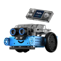
Identifies the CyberPi unit and its integrated features.

mBot2 Shields and Sensors

Lists various mBot2 expansion shields and sensor modules.

Motors and Cables

Details motor types, cables, and connectors for mBot2.

Chassis, Wheels, and Fasteners

Includes the robot chassis, wheels, tires, and fasteners.

Tools and Accessories

Lists essential tools like screwdrivers and track maps.

mBot2 Shield Port Identification

Port 1: Power Switch

Describes the main power on/off switch location.

Port 2: mBuild Port

Identifies the mBuild interface for expansion.

Port 3: Multi-function Port

Details the versatile multi-function port.

Port 4: Servo Port

Locates the dedicated port for servo motors.

Port 5: CyberPi Port

Marks the connection point for the CyberPi.

Port 6: DC Motor Port

Identifies ports for standard DC motors.

Port 7: Encoder Motor Port

Pinpoints the port for encoder motors.

CyberPi Component Identification

Input Components

Covers sensors, buttons, and user interface elements.

Output Components

Details display, LEDs, and speaker for feedback.

Connectivity and Expansion

Lists ports for communication and adding modules.

Sensors

Identifies integrated motion and orientation sensors.

Specific Component Details

Ultrasonic Sensor 2

Details the ultrasonic sensor for distance measurement.

Quad RGB Sensor

Describes the sensor for detecting multiple colors.

Screwdriver Usage

Provides instructions on how to use the included screwdriver.

Assembly Guide

Step 1: Initial Frame Assembly

Shows assembly of the robot's base frame.

Step 2: Attaching Motor Modules

Details mounting the drive motors.

Step 3: Wheel Installation

Illustrates how to attach wheels to the motors.

Step 4: Mounting Electronic Components

Shows placement of main boards.

Step 5: Connecting Sensor Cables

Guides on connecting sensors to ports.

Step 6: Motor Wiring

Explains how to connect motors to the control board.

Step 7: Final Assembly Steps

Covers final connections and checks.

Wiring Tips and User Manual

Wiring Tips

Offers advice for correct electrical connections.

Accessing the User Manual

Provides instructions to find the full user manual.

Safety, Precautions, and Compliance

General Product Safety Precautions

Lists essential warnings for safe product use.

Regulatory Compliance Information

Includes FCC statements and declarations of conformity.