EasyManua.ls Logo

Makita GA9000 User Manual

Makita GA9000
8 pages
To Next Page IconTo Next Page
Page #1 background imageLoading...
Page #1 background image
DOUBLE
INSULATION
Disc Grinder
230 mm (9”) MODEL GA9000
SPECIFICATIONS
Model GA9000
Depressed center wheel diameter .................................................................................................. 230 mm (9”)
No load speed (min
-1
)................................................................................................................................ 6,500
Overall length................................................................................................................................ 433 mm (17”)
Net weight ................................................................................................................................ 6.0 kg (13.2 lbs)
Due to our continuing program of research and development, the specifications herein are subject to change
without notice.
Note: Specifications may differ from country to country.
Power supply
The tool should be connected only to a power supply of the same voltage as indicated on the nameplate, and can only
be operated on single-phase AC supply. They are double-insulated in accordance with European Standard and can,
therefore, also be used from sockets without earth wire.
Question and Answer IconNeed help?

Do you have a question about the Makita GA9000 and is the answer not in the manual?

Makita GA9000 Specifications

General IconGeneral
Power SourceCorded Electric
No Load Speed6, 600 RPM
Amperage15 A
Voltage120 V
Wheel Diameter9 inch
Arbor Size5/8 in
Spindle Thread5/8" x 11 UNC

Summary

SPECIFICATIONS

Model and Key Specifications

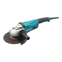
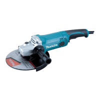
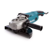
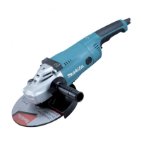
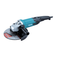
Details the disc grinder's model, wheel diameter, no load speed, overall length, and net weight.

Power Supply Requirements

Outlines the necessary power supply voltage and emphasizes the tool's double insulation feature.

General View Explanation

Disc Grinder Component Identification

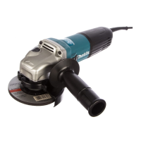
Labels and identifies the various external parts of the disc grinder as depicted in the diagrams.

SAFETY INSTRUCTIONS

Work Area and Personal Safety Guidelines

Covers safety for the work environment, preventing electric shock, keeping children away, and personal protection like clothing and eyewear.

Safe Tool Handling and Maintenance

Focuses on proper tool usage, avoiding forcing, securing work, and essential maintenance practices to prevent injury.

Specific Operational Safety Rules

Details additional safety precautions, warnings on accessory use, repair safety, and hazards like sparks and hot surfaces.

OPERATING INSTRUCTIONS

Installing the Wheel Guard

Step-by-step instructions for correctly mounting the wheel guard to the grinder, ensuring proper alignment and secure fastening.

Attaching the Side Grip (Auxiliary Handle)

Guidance on securely fitting the auxiliary side grip for improved handling and better control during operation.

Installing Depressed Center Wheel

Procedure for mounting a depressed center wheel, including the use of inner/outer flanges and tightening the super nut.

Installing Cut-off Wheel

Steps for mounting and removing cut-off wheels, detailing flange orientation and lock nut tightening procedures.

Switch Operation and Safety Checks

Ensures the switch functions correctly before use, covering the lock-off button and trigger operation for safe starting and stopping.

Grinder Operation Technique

Provides guidance on the correct operating angle, break-in for new wheels, and warnings against forcing the tool for safe grinding.

MAINTENANCE

Replacing Carbon Brushes

Instructions for replacing worn carbon brushes, emphasizing the need to replace both identical brushes simultaneously.

ACCESSORIES

Recommended Accessories Overview

Presents a visual list of recommended accessories for the disc grinder, aiding in selection and understanding of optional parts.

Related product manuals