9 ENGLISH
OPERATION
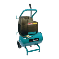
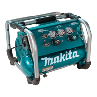
Description of operation
WARNING: Risk of Noise
• Wear hearing protection to protect your
ears against exhaust noise and noise during
operation.
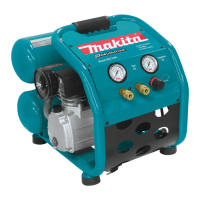
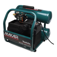
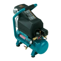
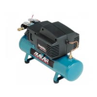
Drain valve:
The drain valve is located at the bottom of the air tank
and is used to drain condensation at the end of each use.
Thermal circuit breaker:
The electric motor has a manual reset thermal circuit
breaker. If the motor overheats for any reason, the
to cool before pushing the reset button and restarting
the compressor.
Motor thermal overload protector:
When the current rating of the motor is exceeded
automatically. The motor must be allowed to cool down
before restarting. The compressor will automatically
restart after the motor has cooled down.
If you are using an extension cord, the compressor
case, the extension cord is too long or narrow. Replace
the extension cord with proper length and width.
ON/AUTO - OFF switch:
Turn this switch to “on” position to provide automatic
when compressor will be left unattended.
WARNING:
OFF switch when not in use.
CAUTION:
ON/AUTO - OFF switch.
Air compressor pump:
To compress air, the piston moves up and down in the
cylinder. On the down stroke, air is drawn in through the
air intake valve. The exhaust valve remains closed.
On the upstroke of the piston, air is compressed. The
intake valve closes and compressed air is forced out
through the exhaust valve, through the outlet tube,
through the check valve and into the air tank. Useable
air is not available until the compressor has raised the
air tank pressure above that required at the air outlet.
Check valve:
When the air compressor is operating, the check valve
is “open”, allowing compressed air to enter the air tank.
When the air compressor reaches “cut-out” pressure,
the check valve “closes”, allowing air pressure to remain
inside the air tank.
Pressure switch unloading valve:
The pressure switch unloading valve located on the
side of the pressure switch, is designed to automatically
release compressed air from the compressor head and
the outlet tube when the air compressor reaches “cut-
out” pressure.
Pressure switch:
The pressure switch automatically starts the motor
when the air tank pressure drops to the factory set
“cut-in” pressure. It stops the motor when the air tank
pressure reaches the factory set “cut-out” pressure.
Safety valve:
-
sor at its “cut-out” pressure setting, the safety valve
will protect against high pressure by “popping out” at
its factory set pressure which is slightly higher than the
pressure switch “cut-out” setting.
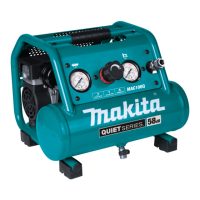
Outlet pressure gauge:
The outlet pressure gauge indicates the air pressure
available at the outlet side of the regulator. This pres-
sure is controlled by the regulator and is always less or
equal to the tank pressure.
Tank pressure gauge:
The tank pressure gauge indicates the air pressure in
the tank.
Regulator:
The air pressure coming from the air tank is controlled
by the regulator knob. Turn the knob clockwise to
increase pressure and counter-clockwise to decrease
a change in pressure setting, always approach the
desired pressure from a lower pressure. When reducing
pressure less than desired pressure. Depending on the
air requirements of each particular accessory, the outlet
you are operating the accessory.
Air outlet:
For regular pressure pneumatic tool, use outlet max
pressure; 0.93 MPa (9.3 bar).
Daily Start-up Checklist
WARNING: Do not use the air compressor
Any air
compressor that cannot be controlled with the switch
is dangerous and must be repaired.
Connecting hoses
WARNING: Risk of Unsafe Operation
• Firmly grasp hose in hand when installing
to prevent hose whip. Losing control of the
hose may result in personal injury and prop-
erty damage.
• Always follow all safety rules recommended
by the manufacturer of hoses, connectors,
air tools, and accessories in addition to
all safety rules for the air compressor.
Following this rule will reduce the risk of
serious personal injury.

 Loading...