IMPORTANT: Retain all shipping bolts, spacers and
grommets Reinstall to prevent damage if you transport
machine in the future.
* Do not plug in power supply until
shipping bolts are removed.
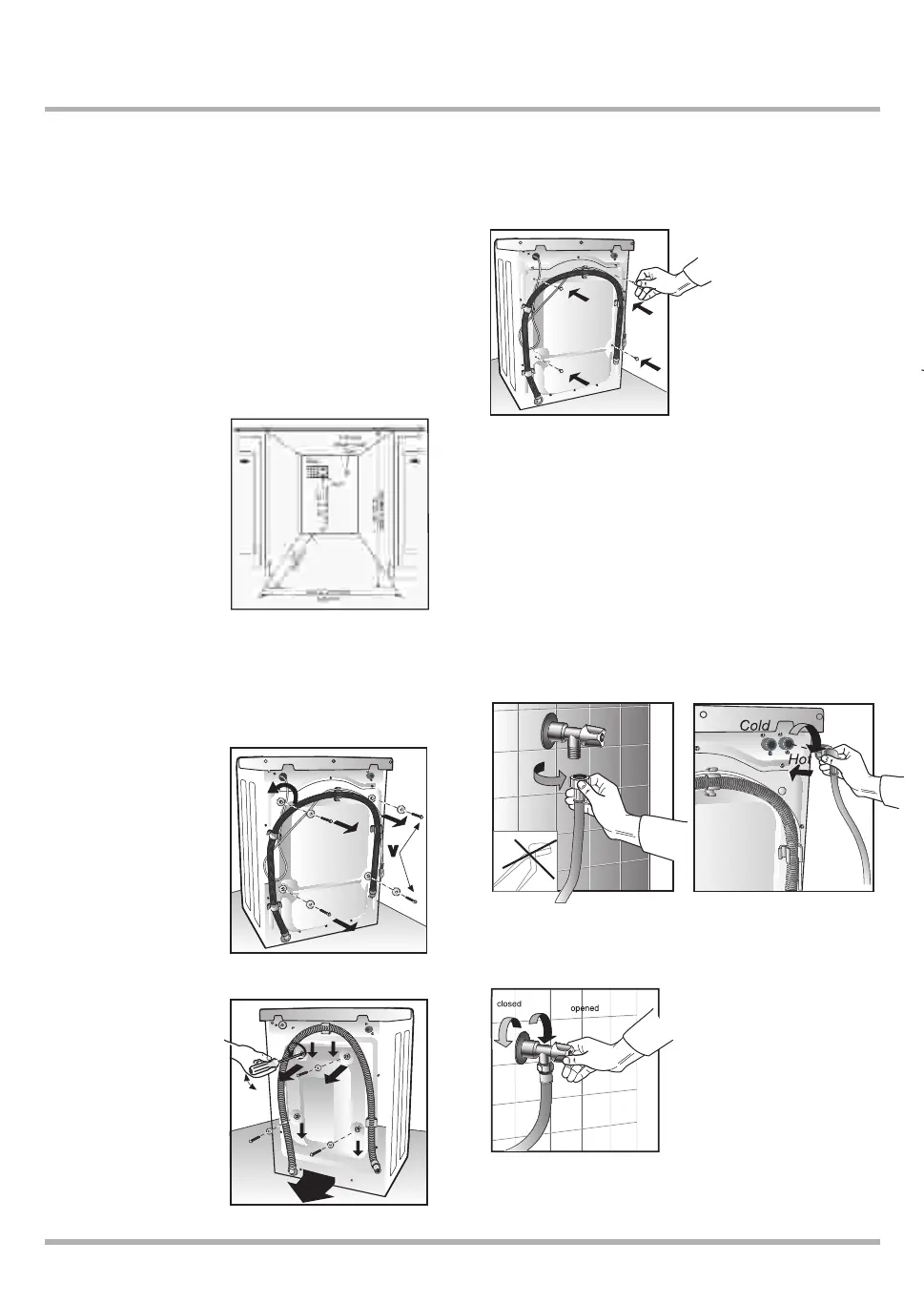
3. Connect Water Inlet
If connecting to new or unused water pipes, run water until clear
before connecting to machine to remove any debris that could clog
the water valve screens. NOTE: Make sure water supply shut-off
valves are easily accessible.
IMPORTANT: Water pressure MUST be within the range of
values indicated in Specifications.
Two inlet hoses are provided with the machine. Hot water hose has
red stripe running the length of the hose. Insert washer/filter (Fig. 5A)
before connecting water inlet hose to valve. Check that other end of the
hose is tight
Connect to faucet (Fig. 5A). Connect to machine (Fig. 5B).
NOTE: connect fill hoses, plastic end to machine AND metal end
to the water faucet.
Turn on water supply (Fig 5C).
Flush out water lines before connecting the hoses to machine.
Installation/Removal
1. Unpack Washing Machine
Move the machine to its installation position. Remove the packing materials
carefully to avoid damage to the machine’s pre installed drain hose and
power cord. Make sure the machine is intact and report any damage to the
retail location you purchased your product from immediately.
WARNING: Destroy the carton and plastic bags after unpacking
Washing Machine. Plastic bags and other packing material are not
children’s toys and can be dangerous.
Built-In Installation
The MALBER P13 e can be installed beneath a cabinet or worktop
with a height of 34-1/2“ ( 876
mm). There must be a gap of
about 1/2“ (12 mm) all around
the machine, including between
the rear edge of the machine
top panel and the back wall.
The opening width must be
at least 24-1/2“ (622 mm).
Space must also be available
for the inlet and drain hoses.
See the diagram above for
measurements and positions.
2. Remove Shipping Bolts/Spacers/Grommets
The machines shipping security consists of shipping bolts (4), spacers
and grommets on the back panel to secure the wash drum during
shipping and delivery.
IMPORTANT: Remove all
shipping bolts/spacers/
grommets before using
the Washing Machine to
allow proper operation
and prevent damage to
the appliance
Failure to remove bolts and
spacers prior to use will
void the warranty.
Once the machine is in its
installation location, remove
the four locking 10mm bolts
and plastic spacers (Fig.1A).
If plastic spacers cannot be
removed, open rear panel (20
torx) screwdriver as shown in Fig
1B, remove spacers and replace
the panel.
Keep bolts, shipping bolts,
and grommets for future
use.
Plug holes with four plastic plugs
enclosed packed with manual
(Fig. 2)
Remove power cord restraints
before plugging in machine.
4
INSTALLATION INSTRUCTIONS
Fig. 1A
Fig. 1B
Fig. 2
IMPORTANT: Do not over-tighten.
Excessive force can damage the
couplings. Tighten by hand; use a
tool only in case of a leak.
spacers
.
I
4. W
Water
siphoni
Wall or
must b
washer.
You sh
allowin
5. Le
The fro
machin
wall or
stable
Once m
IMP
For
perf
Was
mus
on a
or pl
mini
6. C
Plug po
on pag
circuit
into out
NOT
(4) s
prior
ma
c
elec
Do n
sup