1
SL16365A
Set-up:
1. A - Tool Body
B - Foot Assembly (2)
C - Short Legs (2)
D - Long Legs (2)
E - Wing Screws (4)
F - Handle (1)
G - Handle Fasteners (2 nuts and 2 bolts)
H - Hex Wrenches (3)
Instructions
2. Determine desired leg length and insert the appropriate
tube into each foot assembly B, Short Legs: Tube C, produce
a 21-1/4 inch working table height; Tube D, Long Legs, produce
a 29-1/4 inch working table height. Secure leg to foot with
included wing screws E.
3. Insert the other end of each leg/foot assembly into the
receivers on the main body of the tool A so that the feet sit
flush on the ground.
4. Secure the legs to tool body using the included wing screws E.
5. Insert the handle F into the tool as shown above and secure
using included fasteners G. Tighten fasteners until the handle
is securely attached.
6. The tool is now ready for use.
SCSRC1 / SCSRC1 EV
A
C or D
E
SCSRC1
SCSRC1EV
F
A
G
C
D
E
B
H
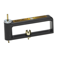
Blade & Die Lateral Adjustment:
The Malco Stone Coated Steel Roofing Cutter is factory adjusted
for optimum performance. In the unlikely event that this tool needs
adjusting to re-establish performance, follow instructions below.
1. Close the tool and insert the cross pin lock J.
2. Locate the 3-M10 flat head screws K around the pivot and, using an
included wrench, loosen these screws 1 to 1-1/2 turns.
3. Locate the 2-M8 set screws L around the pivot and, using an
included wrench, tighten these 2 screws a maximum of 1/4 turn each.
Make sure to tighten each screw the same amount.
4. Retighten the 3-M10 screws K very securely, making sure to cycle
around the screw pattern at least 2 times.
Cross Pin
K
J
L
EN