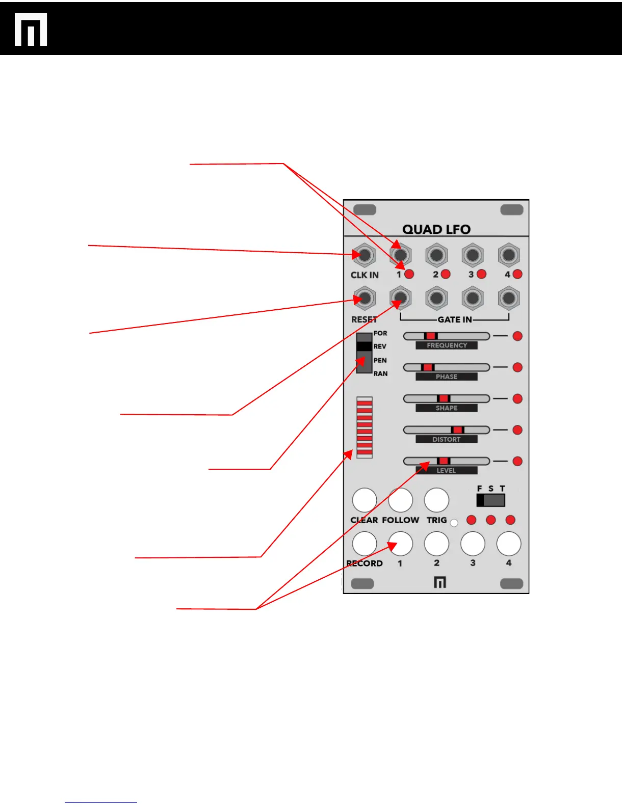
LFO OUTPUT CHANNELS 1-4:
Connect your patch cables from these outputs to other
module CV inputs to modulate them with the QUAD
LFO. There are a total of 4 individual LFOs/outputs, each
with an LED indicating output is active.
CLK IN:
External CLOCK INPUT. Clock input is required for the
animation sequencer to run. Clock is also received from
a Varigate 8+ or 4+ if connected to the same busboard.
Incoming clock also controls LFO tempos set to TEMPO
MODE (see pg.5).
RESET:
Gate input for resetting to step 1 of the animation
sequencer.
- Forward, Pendulum, Random reset to step 1.
- When in Reverse, resets to step 16.
GATE INPUTS:
Each LFO can be re-triggered/restarted with an
individual gate (or cycle without a gate input).
FORWARD/REVERSE/PENDULUM/
RANDOM SWITCH:
Switch to change the direction of sequenced,
automated recording of an LFO. To enable a particular
direction for each of the 4 LFOs, press an LFO channel
select button and then move the switch.
LED BAR GRAPH:
Displays the sequence direction. Each step will pulse
twice for a total of 16 steps.
LFO PARAMETER SLIDERS:
Each of the 4 LFOs include their own set of parameters
that can be adjusted with the sliders. Select LFO buttons
1-4 and then move the sliders to adjust FREQUENCY,
PHASE, SHAPE, DISTORT and LEVEL per LFO.
CONTROLS
QUAD LFO MANUAL V.1
PG. 4
 Loading...