MALLORY IGNITION 550 MALLORY WAY, CARSON CITY, NV 897014
TACHOMETER COMPATIBILITY LIST
Aftermarket White Wire Magnetic Trigger
Tachometer Trigger Connector
Autogage 29074 29078
Autometer
Ford Motorsport
Moroso
Stewart 29074 29078
S.W. & Bi Torx
Sun 29074 29078
VDO 8910 29078
AMC (Jeep) 29074 29078
Chrysler 29074 29078
Ford (Before 1976) 29074 29078
Ford (After 1976) 29074 29078
GM Bypass in-lin Bypass in-line
filter filter
Imports 29074 29078
TROUBLESHOOTING
This section offers several tests and checks you can perform to en-
sure proper installation and operation of the HYFIRE
®
VIA Ignition
Control. If you experience a problem with your HYFIRE
®
VIA, first
check for proper installation and poor connections. You can eliminate
many problems by checking these items. If you have any questions
concerning your HYFIRE
®
VIA Ignition Control contact the Mallory
Technical Service Department at 775-882-6600, Monday through Fri-
day, 8:00 am to 5:00 pm Pacific time.
Tach/Fuel Adapters
If your tachometer does not operate correctly, you probably need a
Mallory tach adapter. Consult the Tachometer Compatibility List at
right for common tachometers and compatible tach adapters.
No-Run on Foreign Vehicles
Some foreign vehicles with fuel injection systems may require a ta-
chometer/fuel injection adapter to run with the HYFIRE
®
VIA Ignition
Control. Often, the same trigger source is used to operate an ignition,
tachometer, and fuel injection. This results in a voltage signal that is
too low to trigger the fuel injection. A tach/fuel injection adapter will
usually solve this problem.
Inoperative Tachometers
If your tachometer fails to operate with the HYFIRE
®
VIA installed, you
may need a Mallory tach adapter. Before purchasing a tach adapter,
try connecting your tachometer trigger wire to the yellow wire of the
HYFIRE
®
VIA Ignition Control. This output produces a 12 volt, square
wave. If the tach still does not operate, you will need a tach adapter.
Two different tach adapters are available:
PN 29078 If you are using the magnetic pickup connector (green
and violet wires) to trigger the HYFIRE
®
VIA, you will
need this adapter.
PN 29074 If your tach was triggered from the coil negative termi-
nal (voltage trigger) and you are suing the white wire
to trigger the HYFIRE
®
VIA, you will need this adapter.
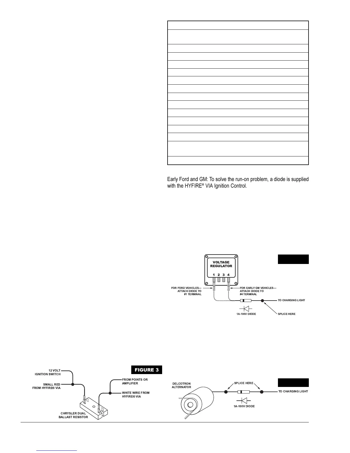
Ballast Resistor
If you have a current trigger tach (originally connected to coil (+) posi-
tive) and use the white wire of the HYFIRE
®
VIA for triggering, you can
purchase a Chrysler Dual Ballast Resistor (1973-76 applications). Wire
it as shown in Figure 3.
Engine Run-On
If your engine continues to run even when the ignition is turned off,
you are experiencing engine run-on. Usually, older vehicles with an
external voltage regulator are susceptible to this condition. Because
the HYFIRE
®
VIA Ignition Control receives power directly from the
battery, it does not require much current to keep the unit energized. If
you are experiencing run-on, it is due to a small amount of voltage
going through the charging lamp indicator and feeding the small red
wire (even if the key is turned off).
GM 1973-83 with Delcotron Alternators
GM Delcotron alternators use an internal voltage regulator. Install the
diode inline on the smallest wire exiting the alternator (see Figure 5).
It is usually a brown wire.
Most other applications: To eliminate run-on, place a resistor in-line to
the HYFIRE
®
VIA small red wire to keep voltage from leaking into the
HYFIRE
®
VIA Ignition.
SMALL RED
FROM HYFIRE® VIA
12 VOLT
IGNITION SWITCH
CHRYSLER DUAL
BALLAST RESISTOR
WHITE WIRE FROM
HYFIRE® VIA
FROM POINTS OR
AMPLIFIER
FIGURE 3
Early Ford and GM: To solve the run-on problem, a diode is supplied
with the HYFIRE
®
VIA Ignition Control. By installing this diode in-line
of the wire that goes to the charging indicator, the voltage is blocked
from entering the HYFIRE
®
VIA Ignition Control. Figure 4 shows the
proper diode installation for early Ford and GM vehicles.
NOTE: Diodes are used to allow voltage to flow only one way.
Make sure the diode is installed facing the proper direction, as
shown in Figure 4.
Ford: Install the diode inline to the wire going to the #1 terminal.
GM: Install the diode inline to the wire going to the #4 terminal.
VOLTAGE
REGULATOR
1 2 3 4
FOR EARLY GM VEHICLES
ATTACH DIODE TO
#4 TERMINAL
FOR FORD VEHICLES
ATTACH DIODE TO
#1 TERMINAL
1A-100V DIODE
TO CHARGING LIGHT
SPLICE HERE
FIGURE 4
DELCOTRON
ALTERNATOR
1A-100V DIODE
TO CHARGING LIGHT
SPLICE HERE
FIGURE 5
 Loading...