EasyManua.ls Logo

Mammoth G-141-MHC User Manual

Mammoth G-141-MHC
20 pages
To Next Page IconTo Next Page
Page #1 background imageLoading...
Page #1 background image
Important: These instructions are for the use of
specially trained personnel, experienced in the
installation of this equipment and related system
components. Some states require licensing of
installation and service personnel. Unqualified
individuals should not attempt to interpret these
instructions or install this equipment. Read
instructions carefully before unpacking, installing and
operating this heat pump unit.
Inspection: This heat pump has been factory
inspected prior to shipment. However, we
recommend you check the carton before unloading
WATER SOURCE HEAT PUMPS
100 Percent Outside Air Units
Sizes 071 thru 381
Installation,
Operation
and Maintenance
Instructions
Mammoth Inc.
www.mammoth-inc.com
U-5
© 1/2003 Mammoth Inc.
(P/N 71144921)
Mammoth is committed to a policy of
continuous. product improvements, and thus
reserves the right to.change specifications and
design without notice.
G - 141 - MHC
Voltage:
F = 208-230/60/3
G = 460/60/3
K = 575/60/3
J = 380/50/3
Unit Size (Nominal Cooling):
071 = 72,250 Btu/hr. cooling
111 = 111,000 Btu/hr. cooling
141 = 148,000 Btu/hr. cooling
181 = 183,000 Btu/hr cooling
221 = 226,000 Btu/hr cooling
271 = 270,000 Btu/hr cooling
321 = 330,000 Btu/hr cooling
381 = 381,000 Btu/hr cooling
Unit Type:
MHC = 100% Outside Air,
Standard Temperature Range
Design Series “C”
MLC = 100% Outside Air,
Low Temperature Geothermal,
Design Series “C”
and note any transit damage on all copies of the bill
of lading. Also inspect the unit for concealed shipping
damage after removing packaging. Transit damage
claims must be filed promptly with the freight
company by the purchaser.
Handling: Always handle with care and in the
horizontal position as shipped on the pallet. Moving
the heat pump on its side or dropping it may damage
internal parts.
Location: Unit must be installed indoors in any area
allowing adequate room for mounting of unit and with
access for maintenance and service.
Nomenclature
Question and Answer IconNeed help?

Do you have a question about the Mammoth G-141-MHC and is the answer not in the manual?

Mammoth G-141-MHC Specifications

General IconGeneral
BrandMammoth
ModelG-141-MHC
CategoryHeat Pump
LanguageEnglish

Summary

Installation, Operation and Maintenance Instructions

Important Information

Key considerations before installation, including inspection and handling advice.

Nomenclature

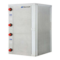
Explains unit model codes for voltage, type, and nominal cooling size.

Installation

Unit Placement Options

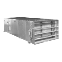
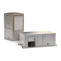
Details on how to place the unit, either suspended from the ceiling or on a flat surface.

Application Limits, Ductwork, Water Supply

Cooling/Heating Limits and Condensate

Specifies temperature limits, condensate trap requirements, and closed loop system preparation.

Ductwork and Water Supply

Instructions for duct connection, insulation, and water supply requirements for the heat pump.

Electric Supply, Controls, and Hose Kits

Electrical Service and Control Wiring

Guidelines for electrical service, fuse sizing, and control wiring compliance with codes.

Optional Hose Kits

Information on stainless steel flexible water hoses for unit connections and proper installation.

Optional Preheat Section

Electric Preheat

Details on the optional electric heater package for preheating outdoor air, including its components and power requirements.

Hot Water Preheat

Information on optional hot water coils for preheating outdoor air, including construction and temperature control.

Wiring Diagrams - General

100% Outside Air Unit Wiring

Presents the primary wiring diagram for the 100% outside air unit, showing electrical connections.

Wiring Diagrams - Circuits

Circuit 2 Wiring and Legend

Details wiring for Circuit #2, including components, legend, and important notes.

Wiring Diagrams - Preheat Options

Hot Water Preheat Wiring

Illustrates the wiring diagram for units equipped with hot water preheat.

Wiring Diagrams - Preheat Options

Electric Preheat Wiring

Shows the wiring diagram for units with optional electric preheat coils.

Wiring Diagrams - Controls

Johnson Metasys Controls with Electric Preheat

Wiring diagram for units using Johnson Metasys controls with electric preheat.

Wiring Diagrams - Controls

Metasys Controls Circuit Details

Provides specific wiring details for Metasys controls, including relays and components.

Wiring Diagrams - Controls

Metasys Controls with Hot Water Preheat

Wiring diagram for Metasys controls combined with hot water preheat systems.

Wiring Diagrams - Combined Systems

Combined Circuit and Control Wiring

Illustrates the combined wiring for unit circuits and control systems, including preheat options.

Optional Temperature Control Systems

DDC Controls (Mammoth & Metasys)

Details on Mammoth DDC and Johnson Metasys DDC controllers for unit operation.

Control by Others and Metasys Sequence

Options for third-party control, and the sequence of operation for Johnson Metasys systems.

Operation and Startup

Startup with Mammoth DDC Controls

Guidance for starting up the unit when using Mammoth DDC controls.

Startup with Johnson Metasys Controls

Step-by-step instructions for starting the unit with factory-mounted Johnson Metasys controls.

Startup with Thermostat Control

Procedures for unit startup when controlled by an external thermostat, including checks.

Maintenance

Air Filter and Coil Maintenance

Instructions for cleaning or replacing air filters and cleaning air coils and blower wheels.

Compressor Protection and Service

Explains compressor protection features and procedures for shutdown and restart.

General Service and Warranty

Information on qualified service personnel, warranty terms, and parts ordering.

Refrigerant Circuit Diagnosis

Normal Operating Conditions

Parameters for subcooling, superheat, pressures, and temperatures under normal operating conditions.

Troubleshooting Refrigerant Issues

Identifies symptoms and parameters for over-charged, under-charged, and TXV issues.

Belt Tensioning Procedure

Setting and Checking Belt Tension

Step-by-step instructions for setting and checking belt tension using a tensioner and deflection force.

Heat Pump Check-Out Sheet

Recording Unit and Operational Data

Fields to record nameplate data and running conditions, including auxiliary heat information.

Related product manuals