Do you have a question about the MANATEC Fox 3D Smart Mobile PT and is the answer not in the manual?
Specifies electrical power requirements for the aligner system and safety precautions.
Details the necessary installation area dimensions, floor conditions, and clearances.
Details the assembly and connection of various equipment components.
Describes the necessary foundation requirements for installing the vertical columns.
Outlines the process for connecting and setting up the computer and related peripherals.
Provides wiring diagrams for connecting various components and routing cables.
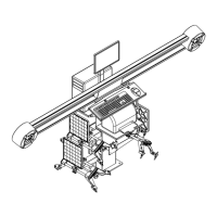
Explains the structure and components of the camera beam and vertical columns.
Describes the function and specifications of the left and right cameras used for image acquisition.
Describes the interface box as a power distribution unit for the system.
Details the motor-driven vertical column for positioning the horizontal beam.
Lists the specifications and requirements for the desktop computer used with the system.
Covers the installation of the main alignment software and its components.
Guides through the installation process for the Windows operating system.
Details the installation steps for the main Wheel Aligner 3D software.
Covers the installation and activation of international vehicle data.
Describes the process of installing and leveling the horizontal beam.
Details the calibration procedure for the dual-axis sensor kit.
Covers the procedures for calibrating the system cameras.
Outlines the steps for performing the four-shaft camera calibration.
Allows checking the visibility and quality of camera images.
Provided to configure the Camera ID for the respective cameras (LH & RH).
Used to adjust camera vision for parallelism and alignment.
Allows selection of vehicle drive type and alignment model.
Details the procedure for replacing defective left and right cameras.
Describes the procedure for replacing components within the interface box.
Outlines procedures for PC installation, software setup, and data restoration.
Presents a high-level overview of the system components and connections.
Provides detailed wiring schematics for different system models.
Addresses common hardware errors and their causes and remedies.
Covers common software errors and troubleshooting steps.
Addresses issues related to incorrect wheel alignment and vehicle pulling.
| Model | Fox 3D Smart Mobile PT |
|---|---|
| Category | Wheel Balancers |
| Rim Diameter | 10"-24" |
| Rim Width | 1.5" - 20" |
| Max. Wheel Weight | 65 Kg |
| Motor Power | 0.37 kW |
| Balancing Accuracy | ±1 g |