The model of this gauge is
F type , only 1 F probe
N type , only 1 N probe
F & N typ e, 1 F & 1 N pr obe
Please read only the related parts in the
manual.
case assures maintenance free performance
for many years.
2 SPECIFICATIONS
Display 4 digits, 10 mm LCD
Range 0~1250 um/0~50mil
Resolution 0.1 um (0~99.9um)
1 um (over 100um)
Accuracy 1~3%n or 2.5 um or 0.1mil
(Whichever is the greater)
PC interface: with RS-232C interface
RS-232C cable & software: not included
(The above are optional accessories)
Power supply 4x1.5 AAA(UM-4) battery
Operating condition: Temp. 0~50 ,
Humidity <80%
Size 126x65x27 mm (5.0x2.6x1.1 inch)
Weight: about 120 g if 1 probe
about 160g if 2 probes
not including batteries
Accessories
Carrying case ...................1 pc.
Operation manual ............ 1 pc.
F probe (if F type) ............1 pc.
N probe (if N type).... ........1 pc.
Calibration foils...............1set
Substrate Iron ............1 pc.
( if F type)
Substrate (Aluminium)......1 pc.
(If N type)
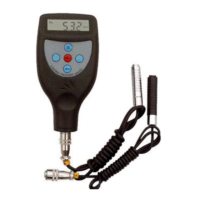
DIGITAL COATING
THICKNESS GAUGE
if 'Fe' on the Display and take the aluminium
substrate if 'NFe' on the Display. Place the probe
(3-1) on the substrate steadily. Press the zero
key (3-3) and '0' will be on the Display before
lifting the probe. If pressing the ZERO key but
the probe is not placed on the substrate or an
uncoated standard, the zero adjustment is
invalid.
5.2 Select an appropriate calibration foil according
to your measurement range.
5.3 Place the standard foil selected onto the substrate
or the uncoated standard.
5.4 Place the sensor (3-1) mildly onto the standard
foil and lift. The reading on the display is the
value measured. The displayed reading can be
corrected by pressing the plus key (3-4) or minus
key (3-5) while the probe is away from the
substrate or the measured body.
5.5 Repeat step 5.4 until the result is correct.
6. BATTERY REPLACEMENT
6.1 When it is necessary to replace the battery, the
battery symbol ' ' will appear on the Display.
6.2 Slide the Battery Cover ( 3-8) away from the
instrument and remove the batteries.
6.3 Install the batteries (4x1.5v AAA/UM-4)
correctly into the case.
6.4 If the instrument is not to be used for any
extended period , remove batteries.
7. CONSIDERATIONS
7.1 In order to weaken the influence of the measured
material on the accuracy of measurement, it is
recommended that the calibrations should be
done on the uncoated material to be measured.
7.2 Probes will eventually wear. Probe life will
- +- +
5
2
10. Notes
10.1 Settings includes restoring factory setting, unit
setting, S/C setting, which should be done within
6 seconds at every stage. or the gauge will quit
itself and keep its status before.
10.2 It is strongly recommended that no changes
should be made to the value of Ln (controlled
by power key, It takes about 11 seconds from
starting depressing Power key. Its value can be
changed by plus/minus key after displaying Ln
and releasing the power key. Store its value and
quit by pressing Zero key.) which will seriously
affect the accuracy. Its value can be adjusted
by professional persons only under the cases of
replacing a new probe or making the gauge more
accurate. Generally, the larger the value of Ln, the
smaller the reading on a same thickness. A little
variation of value of Ln will cause a great change in
reading at high end (e.g. at 500 um/20mil). The
rules to adjust the value of Ln are as follow:
A. Reading at low end can be adjusted to the exact
value by the plus or minus key.
B. To enlarge the Ln if readings at low end ( e.g. at
51 um) is ok but reading at high end (e.g. at
432um) is too large. On the contrary, to decrease
the Ln if reading at low end ( e.g. at 51 um) is ok
but reading at high end (e.g. at 432um) is too
small .
C. Repeat procedures from A to B till the readings
on the every standard foil are satisfying the
accuracy.
7