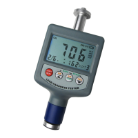
4.6.2 Placement
Holding the tester between your thumb and index finger, hold the tester
against the Work piece. Please note: the impact device must be firmly
against the surface and the impact direction should be vertical to the
testing surface or you may get unsatisfied value.
4.6.3 Releasing
Press the release button lightly on top of the tester and take
measurement. The measuring value will be displayed on LCD. To be sure
that while releasing the triggering button, the work piece, the impact
device and the impact body are all stable and the starting force coincides
with the axis of the impact device.
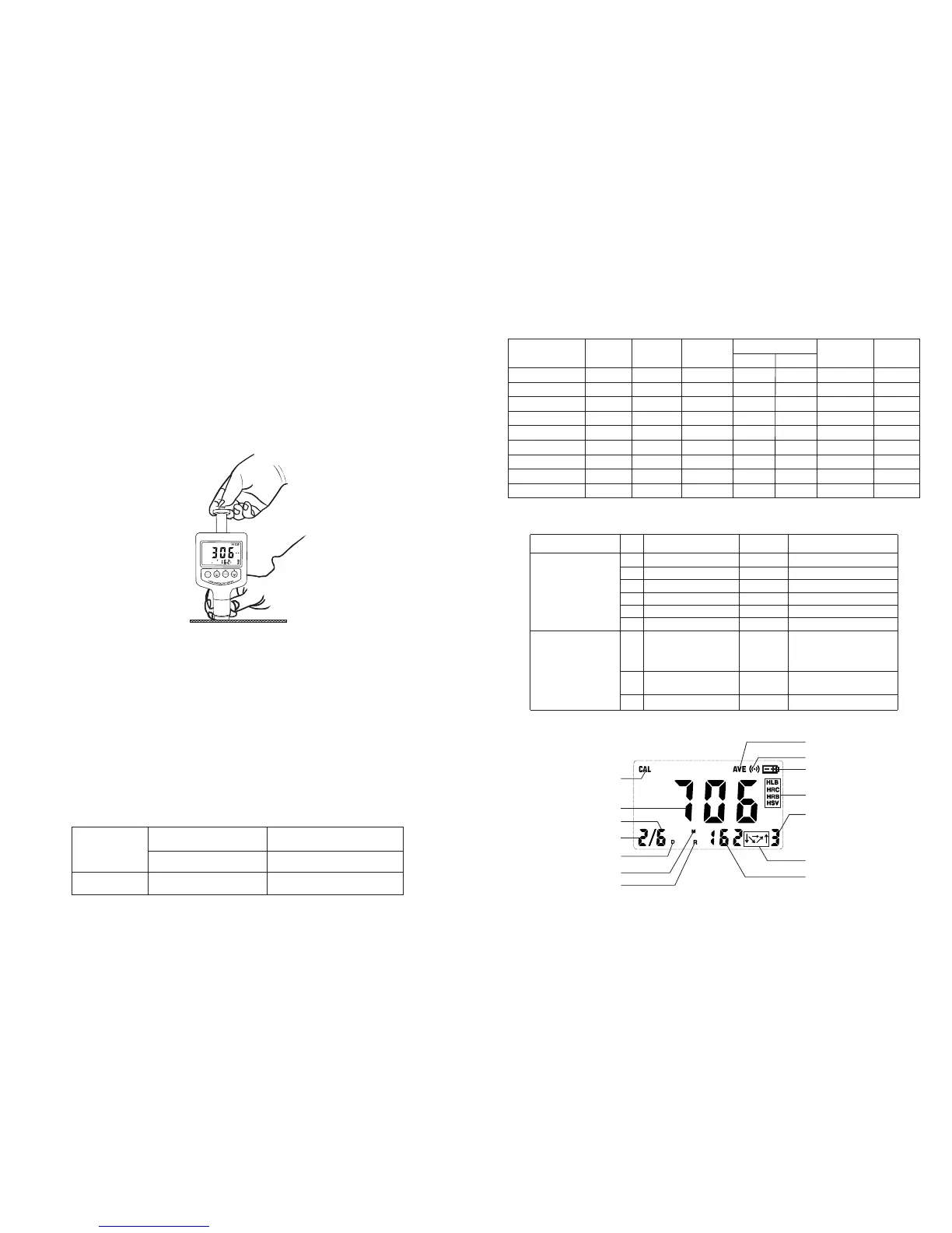
POWER
MENU
RD
DIR
SHIFT
DEL
MATE
SCAL
E
If the test results are outside the ranges listed in Table 1.1, the screen
will display E.
Note: Under no circumstances should you press the release button
if the tester was not against the work piece. Otherwise the support
ring would be loose easily.
Each measure area of the sample usually needs 3 to 5 times of testing
operation. The result data dispersion should not more than mean
value±15HL.
The distance between any two impact points or from the center of any
impact point to the edge of testing sample should conform to the
regulation of Table 4.1
If want accurate conversion from the Leeb hardness value to other
hardness value, Just operate as per procedures listed in part 4.4
Table 4.1
Not less than (mm)
Not less than (mm)
D
3
5
Type of Impact
Device
Distance of center of the
two indentations
Distance of center of the
indentation to sample edge
9
Fig 4.4
1.4 Measuring and Converting Ranges
Table 1.1
Material
HL
HRC
HRB
HB
HS
HV
2
30D
2
10D
Steel & Cast St.
C.W. Tool Steel
ST.STEEL
Gray Cast Iron
Nodular Cast Iron
Cast Aluminum
Brass
Bronze
Copper
80~940
80~898
80~802
32.5~99.5
20~159
45~315
60~290
40~173
80~647
85~655
93~334
131~387
300~900
200~690
300~700
200~550
174~560
400~660
360~650
300~800
300~840
20.0~68.0
38.4~99.5
20.4~67.1
19.6~62.4
46.5~101.7
13.5~95.3
Table 1.2
2 Structure Feature &Testing Principle
2.1 Structure Feature
1
2
14
4
5
6
7
8
9
10
11
12
13
3
2
Fig 2.1
1.5 Configuration
Standard
Configuration
Optional
Configuration
No.
1
2
3
4
5
Item
Main unit
Cleaning brush
Small support ring
Manual
Carrying case
6
1
2
RS232C or USB
cable +Software
Other type of impact
devices and support
rings
Standard test block
Quantity Remarks
Refer to Table A in
the appendix.
1
1
1
1
1
3
Impact body
Included in the main unit
1