Assembly Section 3-6
ASSEMBLY
© 2004 Alamo Group Inc.
SLR5&7 02/02
LIGHT KIT INSTALLATION
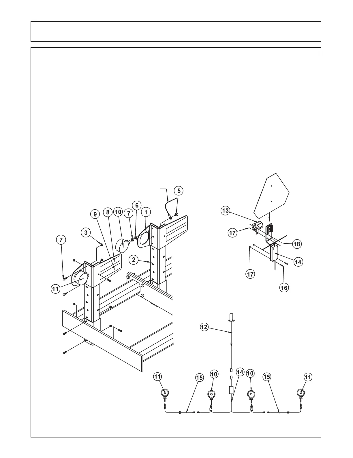
1. Install the upright brackets (#2) on the wing and inside edge of the mainframe using 3/8" x 1" bolts and
locknuts. Install the light brackets (#1) in the uppermost position of the uprights also using 3/8" x 1" bolts and
locknuts. (Ilustration 7).
2. Install the amber lens (#11) in the outermost bracket using the hardware provided. Make sure the bracket is
captured between the two nuts provided. Install the Red light (#10) in a similar fashion to the inner bracket.
(Illustration 9).
3. Install the center wishbone (#14) on the mainframe of the unit attaching the light module to the bracket on the
rear of the three-point mast using the #10 x 1-1/2" pan-head screws, washers, and nuts. Use the provided Ty-
Wraps to route and secure the left and right harnesses to the appropriate light. Install the 5' amber light extension
(#15) between the amber lights and the center wishbone. (Illustration 9).
4. Install the reflector decals as indicated with the fluorescent orang decal (#8) on top and the red reflector (#9) on
the bottom of each light bracket. (Illustration 7).
5. Install the plug holder (#13) on the SMV mount bracket using #10 x 1/2" screw and nuts. (Illustration 8).
6. Install the SMV into the mount bracket.
LH
RH
GROUND WIRE
Illustration 7
Illustration 8
Illustration 9
 Loading...