Do you have a question about the Manfrotto 190XPROB and is the answer not in the manual?
Open tripod legs and adjust height using telescopic extensions and locking lever A.
Utilize the spirit level H to ensure the tripod is properly leveled.
Set each leg to 4 angles of spread by pressing button C to release and lock.
Adjust column height by unlocking knob E, setting desired position, and relocking.
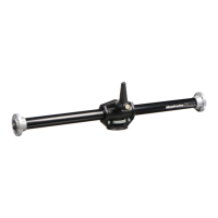
Use the center column in a horizontal plane for shooting directly overhead.
Turn the center column 90 degrees into the horizontal plane using knob E and button Y.
Slide the center column into hole W and lock it securely with knob E.
Return the center column to its vertical position using knob E and button Y.
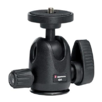
Mount camera head on the center column plate using screw and set screws M.
Hook a counterweight onto ring L for tripod stability in windy conditions.
Utilize the hanging ring T for attaching an optional carrying strap.
Adjust leg extension locking tension using screw P and key N if slippage occurs.
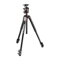
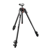
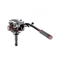
The Manfrotto 190XPROB and 055XPROB tripods are professional-grade photographic accessories designed for versatility and stability across various shooting scenarios. These tripods are ideal for photographers working with small, medium format, digital, or conventional cameras, offering a robust and adaptable platform for capturing images.
At its core, the Manfrotto tripod serves as a stable support system for cameras, minimizing shake and enabling precise framing. Its primary function is to hold a camera at a desired height and angle, allowing for long exposures, macro photography, and situations where a steady hand is not enough. The unique design incorporates a sliding center column that can be operated in both vertical and horizontal planes, providing exceptional flexibility for creative compositions, including overhead shots. Each leg can be independently adjusted to four different angles of spread, adapting to uneven terrain and offering a wide range of shooting heights, including very low angles for floor-level photography. A built-in spirit level ensures accurate leveling of the tripod, which is crucial for panoramic shots and maintaining a straight horizon.
Setting up the tripod is straightforward. To begin, the three tripod legs are opened. The height of the tripod can be adjusted by extending the telescopic leg sections. This is achieved by rotating lever "A" on the locking collar "B" to release the leg extension. Once the desired height is reached, locking lever "A" secures the leg in position. The spirit level "H" is provided to assist in leveling the tripod, ensuring a perfectly horizontal platform for your camera.
The leg angle adjustment is a key feature for adapting to different environments and creative needs. Each leg can be set at four distinct angles of spread. To change a leg's angle, the leg should be closed slightly towards the center column, and the locking button "C" at the top of the leg should be pressed down. While holding the button, the new leg angle can be selected, and releasing button "C" locks it into position. This independent leg adjustment allows for stable setups on uneven surfaces, and the lowest position enables floor-level shooting.
The center column height adjustment offers further control over the camera's position. To release the center column "D," knob "E" must be unlocked. The column can then be adjusted to the required height. Tightening knob "E" locks the column securely in place. For optimal locking, it's recommended to rotate the center column "D" until parts "X" and "Y" align with the locking lever "E."
One of the most innovative features is the horizontal center column. This allows the camera to be offset from the tripod's legs, providing a simple way to shoot directly overhead. To engage this mode, first unlock knob "E" (4.1). Then, push button "Y" and simultaneously raise the center column "D" completely, as shown in figure 4.2. The center column "D" is then turned 90 degrees, as illustrated in figure 4.3, and slid into the hole "W," finally locking it with knob "E" (fig. 4.4).
To return the center column to its vertical position, the process is reversed. Unlock knob "E" and pull out the center column "D" completely (figure 5.1). It is crucial to keep your hand clear of the center column "D" to avoid pinching your fingers (figure 5.2). With one hand, push button "Y" (5.3), and while still keeping your hand clear, rotate the center column "D" back into a vertical position (figure 5.4).
Mounting a camera head is straightforward. First, remove the cap "Z" (fig.1). The camera head is then mounted onto the plate at the top of the center column using the 3/8" mounting screw (clockwise). After raising the center column, the three set screws "M" (supplied unmounted) are tightened against the base of the head with a small screwdriver. Care should be taken not to overtighten them. This feature, especially when used with Manfrotto heads, prevents accidental unscrewing. To remove the head, simply loosen the set screws "M" and unscrew the head from the column (counter-clockwise).
For outdoor use, particularly in windy conditions, the tripod can be stabilized by hooking a counterweight (not supplied) onto the ring "L." This adds stability and prevents the tripod from tipping over. The tripod also includes a hanging ring "T" for an optional carrying strap, making it easier to transport.
The tripod's leg lock tension can be adjusted if the telescopic leg extensions slip even after tightening the locking lever "A." To do this, remove cap "K," release lock lever "A," and then turn screw "P" clockwise using the special key "N" provided on one of the tripod legs. Typically, about a third of a turn will be sufficient to achieve the correct locking tension. This ensures the tripod maintains its stability and reliability over time.
| Material | Aluminum |
|---|---|
| Product color | Black |
| Weight | 1800 g |
|---|---|
| Height (max) | 1460 mm |