1
3
4
1
2
2
B
A
C
B
B A
D
E
C
1
2
5
6
8
3
4
2
1
7
K
K
K
K
K
Z
G
M
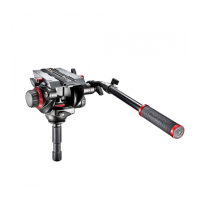
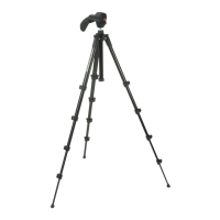
INTRODUCTION
Universal professional stand designed to support camera up to 730 cm / 287.4 in.
KEY FEATURES
• 3 Levelling legs
• 3/8” mounting screw on the top of the column which allows you to fix camera head
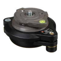
• Spirit level
• Wind bracing kit of 3 ropes
• Column extension collars are pressure die cast aluminium
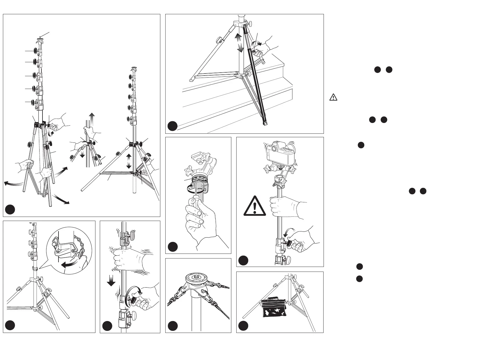
SET UP
Stand must always be set-up on firm ground capable of supporting the weight of both the stand and
the load. The ground should be flat.
HOW TO OPEN THE BASE &
Unlock knob “A” (1), press upper casting “B” down and spread the legs “C” outwards.
To obtain maximum stability, position the leg brace “D” parallel to the ground.
Lock the legs and base by tightening the knob.
Note: It’s also possible to lower the centre column by undoing the lower casting knob “E”
The centre column must never touch the ground as this adversely effects the stability of the
stand.
The stand is supplied with the spirit level “X” dismantled. It can be mounted as shown in figure 2.
USE
HEIGHT ADJUSTMENT &
The stands have telescopic centre column height adjustment.
Locking knobs “K” (fig. 1) are used to secure the columns in place.
Check the column (s) is locked tight (fig. 3) by applying pressure down before loading the stand.
This should be checked regularly.
LEVELLING LEG
The stand is supplied with 3 levelling legs.
When working on uneven ground, each leg can be extended to ensure the stand is levelled (ensuring
the camera is levelled also) at all times.
For levelling proceed as follow:
- Open locking knob “G”
- Extend the leg until the stand is in the vertical position
- Close the locking knob “G”
It is important that the stand is levelled BEFORE loading it with equipment
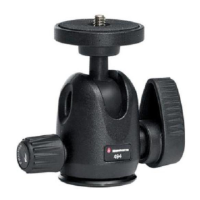
MOUNTING AND REMOVING A CAMERA HEAD &
Never exceed the maximum load: 7 kg / 15.4 lbs.
NOTE
In accordance with DIN 15560 norm, the max load when the stand is fully extended (730 cm/287.4 in)
at an inclination of 6° from vertical is 1 kg / 2.2 lbs.
Remove the cap “Z” (fig. 1)
Mount the camera head on the plate at the top of the centre column via the 3/8” mounting screw
(screw head clockwise). Then raise the column and with a small screwdriver, tighten the three set
screws “M” up against the base of the head, taking care not to force them. This unique feature
works especially well with Manfrotto heads due to the specially designed base, which prevents the
head unscrewing accidentally. To remove the head, loosen the set screws “M” and unscrew the
head from the column (counter-clockwise).
When lowering each telescopic column, firmly support the load and column (fig. 6) by clamping the
relevant column with one hand whilst unlocking knob.
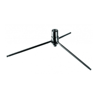
WINDBRACING
For use in the open secure the stand with safety cables as shown in figure.
ACCESSORIES
SAND BAGS (Art. 266 and Art. 267)
Designed to allow more stability: fill with sand or other material and position on stand legs or leg
brace (fig. 8)
1 2
1 3
4
5
7
8
6
 Loading...