EasyManua.ls Logo

Manfrotto 405 - User Manual

Manfrotto 405
6 pages
Print Icon
To Next Page IconTo Next Page
Loading...
D
MODE
D’UTILISATION ET
Les différents réglages de la rotule
sont parfaitement contrôlables
permettant ainsi une très grande
finesse et une grande précision des
trois mouvements (panoramique, de
la bascule, avant/arrère et latérale).
REGLAGES FINS ET
Utilisez les 3 boutons suivants :
“A” - pour le mouvement
panoramique
“B” - pour le réglage du mouvement
de la bascule avant/arrière.
“C” - pour le réglage du
mouvement latéral.
La finesse des réglages est
simplement obtenue en tournant les
boutons (voir fig. 1, 8, 9, 10 et 11). Le
mécanisme de réglage peut être
actionné dans le sens inverse, ce qui
permet de positionner parfaitement
l’appareil photo sans pour cela devoir
débloquer des boutons.
REGLAGES
RAPIDES ET
Utilisez les 3 molettes suivantes:
“D” - pour le mouvement
panoramique.
“E” - pour le réglage du
mouvement de la bascule
avant/arrière.
“F” - pour le réglage du
mouvement latéral.
Le réglage rapide est effectué d'une
main en tournant la molette de
contrôle ("D", "E", "F") sur 90° suivant
les flèches (fig. 11).
Lorsque cette molette est actionnée
d'une main, l'appareil peut alors être
rapidement positionné de l'autre
main.
Pour bloquer la rotule en position,
resserrer la molette de contrôle.
La rotule est livrée avec 3 niveaux à
bulle: "P" pour le mouvement
panoramique (fig. 8), "X" pour la
bascule verticale (fig. 9) et "Z" pour la
bascule horizontale (fig. 10).
EINFÜHRUNG
Der Getriebeneigekopf 405 erlaubt
präzis einstellbare Bewegungen in
drei Richtungen und wurde für
Kleinbild, Mittel- und leichte
Fachkameras entworfen.
AUSSTATTUNGSMERKMALE
Er erlaubt feinste Korrekturen mit
höchster Präzision.
Schnellspannmechanismus mit
Zusatzsicherung
1/4“ und 3/8“ Kamerascharuben
3 Nivellierlibellen
AUFSTELLEN
BEFESTIGUNG
DES KOPFES AUF DEM STATIV
Schrauben Sie den Kopf mit dem
weiblichen Stativgewinde "G" (3/8“).
Die Kopfauflageplatte von
Manfrotto Stativen ist mit den
Blockierschrauben "V" ausgerüstet,
welche ein unerwünschtes
Losdrehen des Kopfes verhindern,
wenn sie korrekt angezogen sind.
ENTFERNEN DER
SCHNELLSPANN-KAMERAPLATTE
VOM NEIGEKOPF UND
Der Blockierhebel “N” ist mit einem
Sicherungsknopf “O” ausgerüstet, der
ein versehentliches Lösen der
Kameraplatte “I” verhindert.
Um die Kameraplatte zu entfernen
gehen Sie wie folgt vor:
- Bewegen Sie den Blockierhebel “N”
(fig. 2) in Pfeilrichtung bis zum
Anschlag.
- Halten Sie den Blockierhebel am
Anschlagspunkt (Pos. 1) fest und
drücken Sie gleichzeitig den
Sicherungsknopf “O” (fig. 3).
- Nun kann der Blockierhebel “N”
noch weiter bewegt werden
wodurch die Kameraplatte “I”
entriegelt wird.
KAMERA PLATTEN SCHRAUBE
Die Schnellspannplatte “I” wird mit
1/4“ “L” und 3/8 “H” Zoll Schrauben
ausgeliefert.
Um die ungebrauchte Schraube zu
entfernen:
- Entfernen Sie den Gummi Stöpsel
“M” indem Sie ihn vorsichtig mit
dem Finger herausdrücken.
- Entfernen Sie die Schraube “L” oder
"H”.
- Bringen Sie den Gummi Stöpsel
F
INTRODUCTION
La rotule offre des mouvements
micrométriques dans les trois
directions.
Elle est conseillée pour l'utilisation
des appareils 35 mm SLR et moyen
format.
CARACTERISTIQUES
Un système unique de réglage
micrométrique de chaque
mouvement permet une très
grande précision d’utilisation,
inégalée à ce jour.
Système de plateau rapide avec
double sécurité
2 vis de fixation 1/4" et 3/8"
3 niveaux à bulle
PREPARATION
MONTAGE DE LA
ROTULE SUR LE TREPIED
Montez la rotule sur le trépied ou
monopode etc. en la vissant grâce
au pas de vis femelle 3/8" " G".
Les disques de base des trépieds
Manfrotto sont dotés de trois vis
sans têtes "V", qui une fois
qu'elles sont en butée sur la base
de la rotule évitent son
desserrage et en assurent sa
parfaite fixation.
DEMONTAGE
DU PLATEAU RAPIDE
DE LA ROTULE ET
Le levier “N” est muni d’une
gâchette de sécurité “O”, ce qui
évite tout décrochage accidentel du
plateau rapide.
Pour fixer le plateau rapide “I”:
- Poussez le levier “N” (fig. 2) dans
le sens indiqué par la flèche
jusqu’a ce qu’il soit en butée.
- Maintenez le levier “N” dans la
position 1 et appuyez sur la
gâchette “O” (fig. 3).
- Continuez à tourner le levier “N”
et retirez le plateau “I”.
VIS SUR LE PLATEAU RAPIDE
Le plateau rapide “I” est livré avec
la vis “L” 1/4” ainsi que la vis “H”
3/8”.
Pour retirer la vis non utilisée:
- Retirer le bouchon d’arrêt en
caoutchouc “M” par une simple
pression du doight
- Retirer la vis “L” ou “H”
- Repositionner le bouton d’arrêt en
caouthchouc afin d’empêcher la vis
de tomber
Sous le support plateau peut etre
stochée la vis non utilisée 1/4” ou
3/8”.
FIXATION DE L'APPAREIL
SUR LE PLATEAU
Fixez l'appareil sur le plateau "I" en
vissant la vis "H" ou "L" de ce
dernier dans le filetage de votre
boitier SANS FORCER .
La vis "H" ou "L" coulisse dans la
rainure "R" permettant d'aligner
l'objectif de l'appareil avec le
plateau "I" et également d'équilibrer
parfaitement l'ensemble de
l'équipement.
Note: La rainure des vis “H” et “L”
permet d’ utiliser une pièce de
monnaie pour leur serrage.
Note: Le plateau "I" (fig. 1) est
également livré avec les deux vis de
fixation, 1/4" "S" et 3/8" "T".
MONTAGE DE L'APPAREIL
SUR LA ROTULE ET
Insérez le plateau situé sous
l'appareil "I" (fig. 5) dans les
queues d'aronde "U" au
sommet de la rotule et ensuite
appuyez sur le plateau "I"
jusqu'à ce que le levier de
blocage "N" fasse un petit
bruit et se ferme.
Assurez - vous que le plateau
"I" (fig. 6) soit parfaitement
bloqué en repoussant le levier
"N" vers la gauche et en
vérifiant que la caméra soit
correctement fixé sur la rotule
en toute sécurité.
RETIRER L'APPAREIL
DE LA ROTULE
Chaque fois que vous devez
retirer l'appareil de la rotule,
tenez votre appareil d'une
main et actionnez le levier de
blocage "N" ainsi que le levier
de sécurité "O" de l'autre
main.
GEBRAUCH UND
Der Kopf ist mit Fein- und
Grobverstellfunktionen ausgerüstet,
die 3 verschiedene
Kamerabewegungen erlauben
(horizontal, vertikal, seitliches Kippen).
FEINVERSTELLUNG
UND
Um feine Kamerabewegungen zu
realisieren, können Sie folgende
Drehknöpfe betätigen :
- “A” Horizontalbewegung
- “B” vertikale Neigebewegung
- “C” seitliche Kippbewegung
Diese Feinverstellungen können
vorgenommen werden, indem Sie
einfach die Drehknöpfe in der
gewünschten Richtung verstellen
(siehe fig. 8, 9 und 10). Die
Verstellungen sind selbsthemmend.
Dadurch muss eine vorgenommene
Verstellung nicht noch zusätzlich
blockiert werden, wie die bei den
meisten Kameraköpfen der Fall ist.
SCHNELLVERSTELLUNG
UND
Um schnelle Kameraverstellungen zu
realisieren, können Sie folgende
Blockierringe lösen:
- “D” Horizontalbewegung
- “E” vertikale Neigebewegung
- “F” seitliche Kippbewegung
Eine schnelle Ausrichtung bis 90°
erfolgt hierbei durch Drehen des
jeweiligen Kontrollrades ("D", "E", "F")
in Pfeilrichtung (fig. 11).
Hält man das Kontrollrad geöffnet,
kann die Kamera rasch bewegt und
mit der andern Hand in die
gewünschte Position gebracht
werden. Um nun den Kopf zu
blockiern muss nur das Kontrollrad
losgelassen werden.
Der Kopf wurde mit drei
Nivellierlibellen ausgerüstet: "P" für
die Panoramabewegung (fig. 8), "X"
für Hochformateinstellung (fig. 9) und
"Z" für die horizontale Ausrichtung.
J
0
330
3
0
0
270
240
210
180
150
12
0
90
6
0
30
Made in Italy
wieder an, damit die Schrauben nicht
verloren gehen.
Der Stativkopf besitzt 1/4“und 3/8
Zoll Gewinde für die Aufnahme der
nicht gebrauchten Schrauben.
AUFSETZEN DER
KAMERA AUF DER PLATTE
Setzen Sie die Platte "I" auf die
Unterseite der Kamera und fixieren
Sie die beiden Elemente, indem Sie
die Verbindungsschraube "H" oder
"L" OHNE GROSSE
KRAFTANWENDUNG in das
Innengewinde der Kamera schrauben.
Die Schraube "H" oder "L" kann
entlang des Schlitzes "R" verschoben
werden. Dadurch kann die Platte "I"
auf das Kameragehäuse ausgerichtet
werden, um die beste
Balanceposition zu finden.
HINWEIS: Die Kameraschrauben “H”
und “L” können mit einer Münze an
der Kamera befestigt werden.
HINWEIS: Die Kameraplatte "I" (fig. 1)
verfügt zusätzlich über ein 1/4" "S"
und ein 3/8" "T" Innengewinde.
BEFESTIGEN DER KAMERA
AUF DEM NEIGEKOPF UND
Setzen Sie die Kameraplatte “I“
in die seitlichen Halterungen
“U“ ein und drücken Sie die
Kamera herunter bis der
Sicherungshebel “N“ einklinkt
und schliesst.
Versichern Sie sich, dass die
Platte “I“ (fig. 6) komplett
blockiert. Drücken Sie dazu den
Hebel "N" ganz nach links
drücken und kontrollieren Sie
nochmals, dass die Kamera
sicher auf dem Neigekopf
festklemmt.
ENTFERNEN DER
KAMERA VOM NEIGEKOPF
Immer wenn Sie die Kamera von
Neigekopf entfernen, müssen
Sie diese mit einer Hand sicher
halten. Lösen Sie mit der
anderen Hand den Hebel “N“
sowie gleichzeitig die
Sicherungstaste “O“.
1
1
2 3
4
1 8 9 10 11
1 8 9 10 11
1 8 9 10
7
5 6
1
1
2 3
4
1 8 9 10 11
1 8 9 10 11
1 8 9 10
7
5 6
1
2
1
4
5 6
7
1 8 9 10 11
1 8 9 10 11
3
LEN
S
LENS
0
330
3
0
0
270
2
40
210
180
150
1
2
0
90
6
0
30
Made in Italy
R
I
H/L
ISTN H
F
O
L
O
N
O
N
I
I
D
C
E
B
V
A
G
N
Q
U
M
1
2
3
16 cm 1,6 kg 7 kg
6 1/4” 3.5 lbs 15 lbs
INSTRUCTIONS
405
1
2 3
4 5
Cod. 405,28 - 09/04 Copyright © 2004 Manfrotto Bassano Italy
Question and Answer IconNeed help?

Do you have a question about the Manfrotto 405 and is the answer not in the manual?

Summary

Introduction

Key Features

Highlights geared movement, quick release plate, camera screw types, and spirit levels for camera control.

Set Up

Assembling Head on Tripod

Attaching the head to a tripod using the 3/8" female thread and set screws for secure locking.

Remove Quick Release Plate

Releasing the camera plate using the locking lever and safety button to prevent accidental detachment.

Plate Camera Screw Management

Handling 1/4" and 3/8" camera screws and their storage on the quick release plate.

Camera Mounting

Assembling Camera on Plate

Fixing the camera onto the quick release plate using the correct screw for optimal balance.

Mounting the Camera on the Head

Inserting and securing the camera plate into the head's dovetail sides using the locking lever.

Remove the Camera from the Head

Safely detaching the camera from the head while holding it securely with the locking and safety levers.

Adjustments

Fine Adjustment

Using control knobs for precise geared movement in pan, tilt, and levelling for accurate positioning.

Rapid Adjustment

Quickly positioning the camera using control wheels, then locking the head in place by releasing rings.

Overview

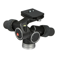
The Manfrotto 405 geared head is a precision instrument designed for photographers who require fine control over camera positioning. It offers precise geared movement in three directions, making it suitable for 35mm SLR, medium, and large format cameras. This head is engineered to provide both rapid adjustments for quick setup and fine-tuned movements for critical alignment, ensuring optimal results in various photographic scenarios.

One of the key features of the Manfrotto 405 is its ability to temporarily disengage the gear movement. This allows the user to quickly set the camera in a general position, saving time during initial setup. Once the approximate position is achieved, the geared movements can be re-engaged for final, precise adjustments. This dual functionality offers a significant advantage, combining speed with accuracy.

The head is equipped with a quick release plate system, which includes a secondary security mechanism to prevent accidental camera detachment. The quick release plate, designated as "I," comes with both 1/4" ("L") and 3/8" ("H") camera screws, accommodating a wide range of cameras. To remove an unused screw, the rubber cap ("M") can be carefully pressed out with one finger, allowing access to the screw. After removal, the rubber cap should be replaced to prevent the screw from being lost. The head itself has dedicated 1/4" and 3/8" holes for storing the unused screw, ensuring that it is always at hand when needed.

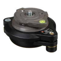
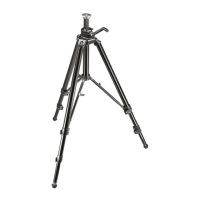
Assembling the head onto a tripod is straightforward. The head features a 3/8" female thread ("G") for secure attachment to most tripods. Manfrotto tripods, in particular, are designed with three set screws ("V") on their top plate. These screws clamp against the base of the head, ensuring an effective and secure lock, which is crucial for stability, especially with heavier camera setups.

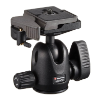
Mounting the camera onto the head involves inserting the camera plate ("I") into the dovetail sides ("U") on the top of the head. The plate should then be pressed downwards until the locking lever ("N") clicks and closes, indicating a secure connection. To ensure the camera is fully locked, the user should push the lever "N" all the way to the left side and verify that the camera is fitted securely. This two-step locking process, involving the lever "N" and a safety button "O," prevents accidental release of the camera plate. To release the camera plate, the locking lever "N" must first be pulled in the direction indicated by an arrow until it goes no further. While holding "N" in this position, the safety button "O" must be pressed simultaneously. This action allows lever "N" to rotate further, thereby releasing the camera plate.

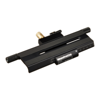
The camera plate "I" itself is designed for optimal camera alignment. The camera screw ("H" or "L") slides along a slit ("R") on the plate, allowing the user to align the camera lens with the plate and choose the best balance position for the camera. The heads of these screws have a groove, enabling them to be tightened with a coin for added security. Additionally, the plate "I" includes 1/4" ("S") and 3/8" ("T") thread attachments for further versatility.

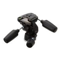
The Manfrotto 405 offers three primary control knobs for fine adjustment: "A" for panning, "B" for tilting, and "C" for levelling. Fine adjustments are made by simply rotating these control knobs. The geared mechanism is designed to hold the camera in position without the need for additional locking once the desired angles are achieved, providing a smooth and stable platform for precise composition.

For rapid adjustments, the control rings ("D" for pan, "E" for tilt, and "F" for levelling) can be rotated through 90 degrees, following the indicated arrows. While holding a control wheel open, the camera can be rapidly repositioned with the other hand to the desired general position. Releasing the control ring then locks the head in place. This feature is particularly useful for quickly changing compositions without losing the precision offered by the geared movements.

To aid in precise levelling and alignment, the head is equipped with three spirit levels: "P" for panning, "X" for vertical portrait format, and "Z" for horizontal position. These spirit levels provide visual cues to ensure the camera is perfectly level in various orientations, which is essential for architectural, landscape, and studio photography.

In summary, the Manfrotto 405 geared head is a robust and versatile tool that combines the speed of rapid adjustment with the precision of geared movements. Its thoughtful design, including a secure quick release system, multiple camera screw options, and integrated spirit levels, makes it an invaluable asset for photographers seeking ultimate control and stability in their work.

Manfrotto 405 Specifications

General IconGeneral
TypeGeared Head
MaterialAluminum
Pan Range/Rotation360°
Quick ReleaseYes
Bubble LevelYes
Tilt Range90°
Base Type3/8"

Related product manuals