Do you have a question about the Manfrotto 494RC2 and is the answer not in the manual?
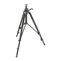
Assemble the ball head on the tripod using the 3/8" female thread and secure locking screws.
Open the lever and safety lever fully to release the quick release plate from the head.
Fix the camera onto the quick release plate by screwing home the camera screw without applying force.
Mount the camera with the plate onto the head and ensure it is fully locked by pushing the lever.
Hold the camera securely while operating the locking lever and safety lever to remove it.
Lock/unlock the ball, adjust friction, and reposition levers for camera positioning.
Learn how to reposition the angle of the locking lever and note that heads are maintenance-free.
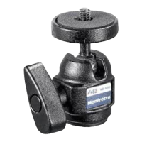
This document describes a ball head designed for use with compact, 35mm, and small digital cameras, offering precise control and secure mounting for photographic equipment.
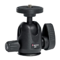
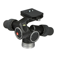
The ball head serves as an interface between a camera and a tripod, allowing for flexible positioning of the camera. Its primary function is to enable smooth and secure adjustments to the camera's angle and orientation. The core mechanism involves a ball (D) that can be freely moved within a socket when unlocked, and then securely fixed in place to maintain the desired camera position. This design facilitates quick and accurate framing for various photographic scenarios.
The head incorporates a separate friction adjustment mechanism, which is crucial for controlling the fluidity of the ball's movement. This feature allows photographers to fine-tune the resistance of the ball's motion, making it easier to compose shots without the camera flopping or moving too freely before it is fully locked. The friction adjustment is independent of the main locking mechanism, ensuring that the camera can be positioned with precision even before the final lock is applied.
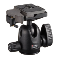
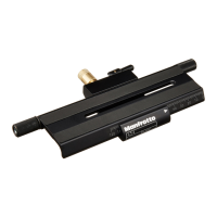
A quick-release plate system is integrated into the design, allowing for rapid attachment and detachment of the camera from the head. This system consists of a plate (G) that attaches to the camera and a receiver on the ball head. The quick-release plate ensures that the camera can be mounted and removed efficiently, which is particularly useful in fast-paced shooting environments. The system includes safety features to prevent accidental release of the camera, enhancing security during use.
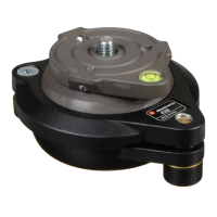
To begin using the ball head, it must first be assembled onto a tripod. This is achieved by screwing the head onto the tripod's 3/8" female thread (A). Many Manfrotto tripods are equipped with three set screws (B) on their top plate. These screws are designed to clamp against the base of the ball head, ensuring a robust and secure connection between the head and the tripod. It is essential to tighten these set screws to prevent any unwanted movement or loosening of the head during operation.
Before mounting a camera, the quick-release plate (G) needs to be detached from the ball head. This process involves opening the main locking lever (H) and the safety lever (I) fully in the direction indicated by the arrow. As these levers are opened, a peg (L) will click up, holding the main lever (H) in its open position. This action releases the quick-release plate, allowing it to be removed from the head.
Once the quick-release plate (G) is removed, it can be attached to the camera. The camera screw (M) on the plate is inserted into the camera's threaded hole. It is important to screw the camera onto the plate without applying excessive force. The ring (Q) on the camera screw assists in tightening the connection. Before fully locking the camera onto the plate, ensure that the camera is properly aligned with the plate (G). It is crucial to securely lock the camera onto the release plate before proceeding to mount it on the ball head, as this prevents accidental detachment and potential damage to the camera.
With the camera securely attached to the quick-release plate (G), the entire assembly can then be mounted onto the ball head. First, push the ring (Q) so that it lies flat against the plate (G). Then, insert the camera plate (G) into the receiver on top of the head. It should slide in smoothly. Once inserted, push the main locking lever (H) to secure the plate. It is vital to ensure that the plate (G) is fully locked and that the camera is fitted securely to the head before use. This can be confirmed by gently testing the camera's stability.
When the camera needs to be removed from the ball head, it is important to maintain a secure grip on the camera with one hand. Simultaneously, operate the main locking lever (H) and the safety lever (I) with the other hand. This two-step process ensures that the camera is released safely and intentionally, preventing accidental drops.
The lever (C) is responsible for locking and unlocking the movement of the ball head. To release the ball (D) and allow for camera positioning, rotate lever (C) counter-clockwise until it reaches the free position. Once the desired camera position is achieved, lock the ball (D) by rotating lever (C) fully in a clockwise direction. This action firmly secures the camera in place.
The ball head includes a separate friction adjustment for the ball movement, which helps in controlling the positioning of the head before it is fully locked. To adjust the friction, first ensure that the ball (D) is not locked by rotating the main locking lever (C) counter-clockwise. Then, hold the camera in one hand and use the other hand to rotate the knob (F). Rotating knob (F) clockwise will tighten the friction, increasing resistance to the ball's movement. Rotating it counter-clockwise will reduce the friction, allowing for smoother movement. It is important to note that the friction adjustment does not lock the camera; it only controls the resistance of the ball's movement. To fully lock the camera, the main locking lever (C) must be turned fully.
The angle of the main locking lever (C) can be repositioned as needed without affecting its locking function. To do this, pull the lever outwards, rotate it to the desired position, and then release it. The lever will then locate itself in the new position, allowing for more comfortable and ergonomic operation based on the user's preference or shooting setup.
The ball heads are designed to be maintenance-free. This means they do not require regular lubrication or special care. It is explicitly stated that users should not lubricate the heads with any oil or silicon. This simplifies ownership and ensures the longevity of the product without the need for complex upkeep. The robust design and materials used are intended to provide reliable performance without external intervention.
| Type | Ball Head |
|---|---|
| Material | Aluminum |
| Quick Release Plate | Yes |
| Secondary Safety System | Yes |
| Tilt Range | 90° |
| Lateral Tilt | 90° |
| Ball Locking | Yes |
| Friction Control | Yes |
| Independent Pan Lock | Yes |
| Independent Tilt Lock | No |
| Pan Drag | Yes |
| Tilt Drag | Yes |
| Color | Black |
| Panoramic Rotation | 360° |
| Load Capacity | 4 kg |
| Height | 7.9 cm |