U
L
L
L
N
A
T
J
V
U
T
2
1
2
M
1
M
2
5
7
8
6
9
10
X
B
ON
OFF
B
L
K
S
E
R
Z
J
G
H
H
F
D
L
N
P
K
M
S
Q
1
2
K/S
N
L
L
2
1
3
4
2
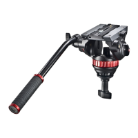
INTRODUCTION
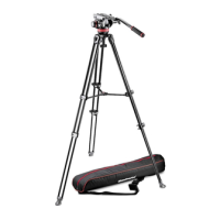
Designed for digital ENG and DVD camcorder and the use of telescopes for
loads up to 6kg.
KEY FEATURES
• Quick release sliding plate for balancing the camcorder with secondary safety latch
• 1/4”W and 3/8”W camera screw and VHS pin
• 3/8” female tripod attachment
• Additional PAN and TILT friction control
• Pan bar can be fitted left or right
• Spirit level for fine levelling
• Counter balance system for a load of approx. 2,5kg/5.5 lbs
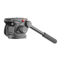
SET UP
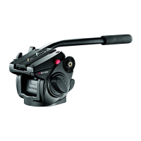
The 501HDV head is supplied with the telescopic pan bar “A” dismantled. It can
be mounted to the either side of the head by unscrewing knob “D” and
screwing it with the casting “E” on the hole “F”.
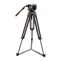
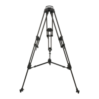
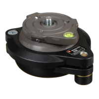
ASSEMBLING HEAD ON TRIPOD
Assemble the head on the tripod using 3/8” female thread “G”. The top plate on
Manfrotto tripods are equipped with three set screws “H” which clamp against
the base of the head to ensure effective and secure locking.
REMOVE QUICK RELEASE PLATE FROM HEAD
Extract plate “L” realising the locking knob “M” whilst pushing button “N” at the
same time as shown in figure 2.
ASSEMBLING CAMCORDER ON PLATE &
The head (fig. 1) is supplied with 1/4” camera screw “K” and 3/8” camera screw
“S”on the plate “L”
To remove the screw not used proceed as follow (fig. 2)
- lightly press the rubber cap “Q” with your finger
- remove the screw not used
- reposition the cap to prevent the screw from being lost
NOTE
The head is provided with threaded housing for the screw not used (hole for
3/8” screw “Z” and hole for 1/4” screw “R” - fig. 1)
Fix the camcorder onto plate “L” (fig. 3) by screwing camera 1/4” screw “K” or
3/8” screw “S” into the camcorder’s threaded hole WITHOUT APPLYING
FORCE (using for example a coin).
If the camcorder has a hole for anti-rotation, insert the pin “P” (fig. 2) on the hole
before screwing camera screw.
Before fully locking, align the camcorder lens with mark “LENS” on the camera
plate “L”.
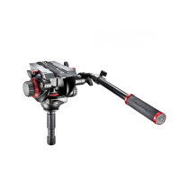
MOUNTING THE CAMCORDER ON THE HEAD &
Insert the camera plate “L” as shown in figure 4 on top of the head until locking
button “N” clicks.
Hold the camcorder during the follow operation to prevent it from slipping
backwards and forwards.
Find the balance point for the horizontally positioned camcorder:
• Level the head on the tripod (you can use both tripods with flat attachment or
levelling bowl) using the spirit level “J” (fig. 1)
• With the locking knob “U” (fig. 5) unlocked and the friction control “T” (fig. 7)
at minimum, slide the camcorder until find the equilibrium point (fig. 5 and 6)
• Lock the plate “L” (fig. 7) in the position reached by screwing the locking knob “M”
1
1
2
2
3
1 4 5
6
7