J RUE KOCN
Cod. 1039260 - 06/14 Copyright © 2014 Manfrotto Bassano Italy
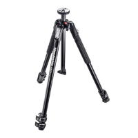
160 cm 2 kg 7 kg
63” 4.4 lbs 15 lbs
INSTRUCTIONS
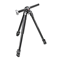
MT190X3
INTRODUCCIÓN
Diseñado para el aficionado avanzado y el
fotógrafo profesional, este es un trípode ex
-
tremadamente versátil, ideal para cámaras
pequeñas o de medio formato, digital o tipo
convencional.
CARACTERÍSTICAS CLAVE:
• Columna central deslizante única que puede
funcionar tanto en vertical como en el plano
horizontal.
• Cada pata puede ser configurada indepen
-
dientemente en 4 ángulos.
• Nivel de burbuja.
• Dos cubiertas térmicas de caucho para las
patas
• Conector Easy-Link para fácil inserción de
brazos
• Palancas de desbloqueo rápido que pueden
abrirse simultáneamente
• Gancho para colgar un contrapeso o una
correa
CONFIGURACIÓN
Y
Abrir las 3 patas del trípode.
Para ajustar la altura del trípode, cada pata
tiene extensions telescópicas que pueden libe
-
rarse abriendo la pinza “A” sobre el collar de
bloqueo “B”.
Sujete las palancas con toda la palma de la
mano. Desbloquéelas todas a la vez.
TENGA CUIDADO de no lastimarse los
dedos al abrir la palanca (fig. 1A).
Cuando se consiga la altura requerida, cierre la
pinza de bloqueo “A”.
AJUSTE DEL ÁNGULO DE LA PATA
Cada pata se puede configurar en 4 ángulos
de apertura.
Para cambiar e lángulo de una pata, junte la
pata hacia el centro de la columna ligeramente
y presione hacia abajo el botón de bloqueo “C”
en la parte superior de la pata. Mientras man
-
tiene el botón hacia abajo, seleccione el nuevo
ángulo de la pata y luego libere el botón “C”
para bloquear en posición. El ángulo de cada
pata puede ser ajustado independientemente
de las otras dos patas. La última posición per
-
mite alcanzar el nivel del suelo.
AJUSTE DE LA ALTURA
DE LA COLUMNA CENTRAL
Para liberar la columna central “D”, desblo
-
quee el pomo “E” y ajuste la altura de la colum-
na como se desee. Apriete el pomo “E” para
bloquear la columna en posición.
PLACA DE SUJECIÓN PARA RÓTULAS
La placa de sujeción para rótulas "F" permite
tomas en ángulos muy bajos sin necesidad de
invertir la columna central.
-oprima el botón "Q" y extraiga la placa de su
-
jeción para rótulas "F"
-libere la palanca "E"
-retire la columna "D"
-monte la placa de sujeción para rótulas "F"
en el trípode oprimiéndola dentro del agujero
central de la parte superior del trípode hasta
que haga clic. Asegúrese que el botón "S"
quede alineado con la parte "V"
-bloquee la placa de sujeción para rótulas "F"
en posición apretando la palanca "E"
Ahora puede Ud. montar la rótula en la placa
para sujeción de rótulas "F".
Para evitar que la placa "F" con rótula y
cámara pueda caerse accidentalmente
del trípode dañando la cámara, es crucial que
la palanca de bloqueo "E" permanezca firme
-
mente apretada todo el tiempo.
Antes de desensamblar, primero quite la rótula
de la placa para sujeción de rótulas "F" y luego
quite la placa para sujeción de rótulas "F" del
trípode aflojando la palanca "E".
Nunca use la placa para sujeción de ró-
tulas "F" en la posición de abajo como
se muestra en fig. 1.
MONTANDO Y QUITANDO UNA RÓTULA
Quite el tapón “Z” (fig.1)
Monte la rótula en la placa situada en la parte
superior de la columna central utilizando el tor
-
nillo 3/8” (atornillando en sentido de las agujas
del reloj). Enseguida, suba la columna central
y con un desarmador pequeño, apriete el tor
-
nillo “M” contra la base de la rótula teniendo
cuidado de no forzar. Esta característica única
funciona especialmente bien con las rótulas
Manfrotto debido a la base especialmente di
-
señada para evitar que la rótula se desatornille
accidentalmente.
Para quitar la rótula, afloje el tornillo “M” y
desatornille la rótula de la columna (en senti
-
do contrario a las agujas del reloj). Enseguida
suba la columna central y con un desarmador
pequeño, apriete el tornillo “M” contra la base
de la rótula teniendo cuidado de no forzar.
NOTA
Para uso en exteriores, especialmente en con
-
diciones de viento, es posible estabilizar el
trípode: cuelgue un contrapeso (no proporcio
-
nado) del anillo “L”.
TRANSPORTE
El trípode tiene un gancho “L”, para una correa
de transporte opcional.
AJUSTE DE LA TENSIÓN
DEL BLOQUEO DE LA PATA
Si las extensions telescópicas de las patas se
deslizan incluso después de haber cerrado la
pinza de bloqueo “A”, será necesario ajustar la
tension de bloqueo. Para hacer esto:
-libere la pinza de bloqueo “A”
-gire el tornillo “P” en el sentido de las
agujas del reloj usando la llave especial
“N” proporcionada en una de las patas del
trípode.
Normalmente un tercio de vuelta sera sufi
-
ciente para conseguir la tensión de bloqueo
correcta.
MONTAJE DE ACCESORIOS
Quite el tapón “K”
El trípode tiene un agujero roscado de 3/8” “X”
(fig. 9) que se puede usar para montar acce
-
sorios, tales como los brazos Manfrotto para
soporte de luces, monitor etc).
MANTENIMIENTO
Para reemplazar el collar de bloqueo “B” (fig.
1), por favor usa una llave TORX número 25 (no
proporcionada con el producto).
1A 1B
2
3
4
5
6
7
8
9
••
••
••
••
••
••
••
&
”B””A”
1A
”A”
”C”
”C”
”D””E”
”E”
"F"
•- “Q”
•“F”
•- "E"
•- “D”
•- "F"
"S"
"V"
•- "E""F"
”F"
"F"
"E"
"E"
"F".
1"F"
”Z”(1B)•
3/8”
”M”
Manfrotto
”M”
”L”
”L”
”A”
•- ”A”
•- ”N”
”P”
1/3
”K”
3/8”(9)
Manfrotto
•"B"•1
No.25•(
1A 1B
2
3
4
5
6
7
8
9
、。
••
•• 4
••
••
•• Easy•Link•
••
••
&
3。
“B”
“A”。
。
。
。
“A”。
4。
“C”。
“C”
。。
。
“D”“E”
。“E”
。
“F”
。
•- “Q”“F”
•- “E”
•- “D”
•- “F”
“S”
“V”
。•
•- “E”“F”
。
“F”
。
“F”
“E”
。
“E”
“F”。
“F”1。
“Z”1
•3/8”•
。
“M”
。
。
“M”
。
“L”
“L”
“A”
。•
•- “A”
•-
“N”“P”。
。
“K”
3/8”
X9
、。
“B”(1)•
TORX•25(
)。
1A 1B
2
3
4
5
6
7
8
9
,
,
.
:
4
2
&
.
,
B
A .
,
.
:
(fig. 1A )
, A .
4
.
,
C .
,
C .
2
.
.
D , E
.
E
.
F
- Q F
.
- E
- D
- F
"S" "V"
- "E" F
.
F
.
F
"E"
.
,
"E"
.
fig. 1 "F"
Z (fig.1)
3/8 (
).
M
.
,
.
M
.
,
:
L .
L
.
A
,
. :
- A .
- N P
.
3 1
.
K .
3/8 X (fig. 9)
,
Arm
.
B (. 1) TORX
25 . (
.)
1A 1B
2
3
4
5
6
7
8
9
ВСТУПЛЕНИЕ
Разработанный для продвинутых любителей и
профессиональных фотографов, чрезвычайно
универсальный штатив идеально подходит для
цифровых и традиционных камер небольшого и
среднего форматов.
ОСНОВНЫЕ ХАРАКТЕРИСТИКИ:
• Уникальная подвижная центральная колонна,
которая может использоваться в вертикальной
или горизонтальной плоскостях.
• Каждая ножка может быть независимо уста-
новлена под 4 различными углами.
• Пузырьковый уровень
• Два резиновых утеплителя ножек
• Разъем быстрого соединения для подсоедине-
ния рукояток.
• Рычаги Quick Power Lock, позволяющие легко и
одновременно открывать все рычаги.
• Крючок для подвешивания противовеса и кре-
пления ремня.
УСТАНОВКА и
Откройте 3 ножки штатива.
Для регулировки высоты штатива каждая ножка
имеет систему телескопического удлинения, для
удлинения необходимо повернуть рычаг “A” на
фиксирующем хомуте “B”.
Возьмите рычага всей ладонью руки. Одновре-
менно отоприте все фиксирующие рычаги.
БУДЬТЕ АККУРАТНЫ, чтобы не прищемить
палец при открытии рычага (см. рис. 1A)
После достижения необходимой высоты, зафик-
сируйте “A”.
РЕГУЛИРОВКА УГЛА НОЖЕК
Каждая ножка может быть установлена под 4
различными углами. Для изменения угла ножки,
слегка закройте её в направлении центральной
колонны и потяните вниз фиксирующую рукоятку
“C”, расположенную в верхней части ножки.
Удерживая нижнюю часть, выберите новый угол
ножки и отпустите рукоятку “C” для фиксации
положения. Угол каждой ножки может регули-
роваться независимо от положения двух других
ножек. Последнее положение позволяет достичь
уровня земли.
РЕГУЛИРОВКА
ВЫСОТЫ ЦЕНТРАЛЬНОЙ КОЛОННЫ
Для того чтобы освободить центральную колонну
“D”, отоприте рукоятку “E” и установите колонну
на необходимую высоту. Затяните рукоятку “E” для
фиксации колонны в нужном положении.
ПЛОЩАДКА ДЛЯ
ПРИСОЕДИНЕНИЯ ГОЛОВКИ
Площадка для присоединения головки “F” позво-
ляет снимать с очень низких углов без необходи-
мости переворачивать центральную колонну.
-нажмите на кнопку “Q” и вытяните площадку для
присоединения головки “F”
-разблокируйте рычаг “E”
-снимите колонну “D”
-установите площадку для присоединения голов-
ки “F” на штатив, вставляя её с усилием в верхнее
отверстие плеча до щелчка, следя за тем, чтобы
кнопка “S” была выравнена с деталью “V”
-зафиксируйте на месте площадку для присоеди-
нения головки “F”, затянув рычаг “E”
Теперь вы можете установить штативную головку
на площадку “F”.
Во избежание случайного падения пло-
щадки “F” с головкой и камерой и повреж-
дения камеры крайне важно, чтобы фикси-
рующий рычаг “E” был постоянно туго
затянут.
Перед разборкой сначала снимите головку с пло-
щадки, а затем снимайте с плеча головку для пло-
щадки, отпустив рычаг “E”.
Никогда не используйте площадку для при-
соединения головки “F” в нижнем положе-
нии так, как показано на рис. 1.
МОНТАЖ И СНЯТИЕ ГОЛОВКИ КАМЕРЫ
Снимите крышку “Z” (рис. 1)
Установите головку камеры на площадку, рас-
положенную на верхней части центральной
колонны при помощи монтажного винта 3/8” (за-
винчивайте площадку по часовой стрелке). Затем
поднимите центральную колонну и с помощью
маленькой отвертки закрутите винт “M” в основа-
нии головки, но не перетяните его. Эта уникаль-
ная характеристика особенно хорошо работает с
головками
Manfrotto, благодаря специально разработан-
ному основанию, которое не допускает возмож-
ность случайного развинчивания. Для того чтобы
снять головку, расслабьте винт “M” и отвинтите
головку с центральной колонны против часовой
стрелки.
ВНИМАНИЕ
При использовании штатива вне помещений,
особенно при сильном ветре, можно стабилизи-
ровать штатив: установите противовес (не входит
в комплект) сверху крючка “L”
ПЕРЕВОЗКА
У штатива есть крючок “L” для транспортировоч-
ного ремня (опция).
РЕГУЛИРОВКА НАПРЯЖЕНИЯ НОЖЕК
Если ножки с телескопическим удлинением сме-
щаются даже после фиксации рычага “A”, необхо-
димо отрегулировать напряжение фиксации. Для
того чтобы это сделать:
-отпустите рычаг “A”
-поверните винт “P” по часовой стрелке при по-
мощи специального ключа “N” , расположенного
на одной из ножек штатива.
Как правило, достаточно одной трети поворота
для достижения правильного напряжения фик-
сации.
КРЕПЛЕНИЕ АКСЕССУАРОВ
Снимите крышку “K”
Штатив оснащен одной внутренней резьбой 3/8”
“X” (рис. 9) , которую можно использовать для
крепления аксессуаров, например, рукояток
Manfrotto, на которые, в свою очередь, можно
устанавливать осветительное оборудование, мо-
ниторы и т.д.
ТЕХНИЧЕСКОЕ ОБСЛУЖИВАНИЕ
Для замены фиксирующего хомута "В" (рис. 1) вос-
пользуйтесь торцевым ключом 25 (в комплект не
входит).
1A 1B
2
3
4
5
6
7
8
9