EasyManua.ls Logo

Manfrotto MT055XPRO3 - User Manual

Manfrotto MT055XPRO3
5 pages
Print Icon
To Next Page IconTo Next Page
Loading...
J RUE KOCN
Cod. 1039133 - 10/13 Copyright © 2013 Manfrotto Bassano Italy


















&


”B””A”




1A
”A”




”C”
”C”




”D””E”
”E”





󰙭

- ”E”(4.1)
- ”Y””D”
4.2

- ”D”90(4.3)
- ”D””W””E”
(4.4)



1.•5.1”E”
”D”

”D”
(5.2)
2.•”D”
”Y”(
5.3)
3.•5.4
”D”
”D”

4.•


  
”Z”(1B)•
3/8”



”M”


Manfrotto


”M”


&

”H”
7



”L”



”L”
 
”A”


”A”
”N”
”P”1/3


”K”

3/8”(11)
Manfrotto

1A 1B
2
3
4
5
6
1B 7
8
9
10
11

󰆦󰁗󰆦󰀶
󰁖󰅶󰁉󰁉󰁠󰅰
、。
󰆗󰄹
󰅰󰆙󰅑
󰇵
󰅇󰅣4󰃻
󰆺

Easy•Link•󰁉

󰁖
󰁉󰁠󰇧󰇵
󰆮
&
3󰅇。
󰅇󰁖
󰃻󰆨󰁠“B”
“A”。
󰂾󰄽󰄈󰅰。󰁖
。

󰅘。
󰅙“A”。
󰅇
󰅇󰅣4󰃻。
󰅇󰅰󰆙
󰅇󰁠󰅇
“C”。
󰂾󰃕󰅇󰅎
“C”。
󰅇。
󰇬󰅣󰅇󰁱。
󰅰󰆙
󰅰󰆙“D”“E”
󰅰󰆙。“E”
󰅰󰆙。
󰅰󰆙
󰅰󰆙󰁉󰄤
󰅇󰅣󰓻
󰅶󰅑󰇬
- “E”(4.1)
- “Y”󰅰
󰆙“D”󰅑󰅡󰆙4.2
。
- 󰅰󰆙“D”󰆨90°4.3
。
- 󰅰󰆙“D”“W”󰅰
“E”4.4。
󰅑󰅰󰆙
󰅰󰆙󰆮󰂾󰅑󰅣
󰆈󰇵
1.•“E”󰅰󰆙“D”
5.1。
󰁉󰆟󰅰󰆙“D”󰆟
󰅘5.2
2.•󰁉󰅛“Y”󰅛
󰅰󰆙“D”(5.3)
3.•󰅛󰅰󰆙“D”󰁉
󰅛󰅑󰅣󰆨󰅰󰆙“D”
5.4。
4.•󰆨󰅰󰆙󰅑󰅡󰆙󰁱󰆝
󰅎󰅰󰆙。
󰆮󰂪
“Z”1
󰁉•3/8”•󰄭
󰂪󰆮󰂾󰅰󰆙。󰅎
󰅰󰆙󰁉“M”
󰂾󰂪󰇷󰆠󰀊󰁉。
󰄤󰅶󰁉󰁠󰂪
󰀚󰄤󰆦󰇷󰁖󰅙󰂪
󰀊。
󰂪“M”󰂪
󰅰󰆙󰄭。

&
󰁖󰆺“H”
。
7󰆺󰅄󰇬
󰁉。
󰆠
󰂾󰁉󰁎󰂾󰁖󰁉
󰁉󰇧
󰂾“L”
󰂯
󰁖󰁉
“L”
󰅇󰄇
“A”󰅇
󰃻󰄇。•
󰄇
- “A”
- 󰁉󰅰󰅇󰆦󰁉
“N”󰄭󰆨“P”。
󰆨󰅎󰅼󰇡
󰄇。
󰆮
“K”
󰁖󰁉󰆮3/8”
X11󰁉󰁠󰅇󰄗
、。
1A 1B
2
3
4
5
6
1B 7
8
9
10
11
 
󰄴󰀂 󰂑 󰅀 󰃦   󰀷
 󰉦󰇵󰉊 󰊥 󰀕󰀉 󰀿󰉽, 
 󰊜 󰋛󰀇 󰊜, 󰀖 󰁸󰋉 󰆺
󰀂 󰂏󰇡  󰀊 󰅞 󰊜
 󰀶󰊢󰊢.
󰁯:
󰈞󰀂 󰀇 󰇞 󰅶   
 󰄵  
󰀂  4󰂏󰀂   󰁏
󰀸 
󰉦 󰁱
2󰀂   
Arm   󰀑 󰀇󰂏 󰆺 󰆂
      󰀑 󰊜 󰆯
󰈳  
󰉡󰊭󰄴 󰈝   󰀑 

&
󰈝󰀇󰉦󰀂   󰉝󰅛.
󰈝󰀇󰉦󰀂 󰀇 󰁏󰀸󰊜,  
󰂏 󰀑 󰄴 󰀠  󰀸 B󰀂 
 A  󰁯 .
  󰀷󰄑  󰁾 󰋯,  
󰇈  󰉻󰁶.
󰁯󰀂󰊤:   󰀇 󰀇󰂏
 󰀂 󰊜 (fig. 1A 󰃳)
󰊜 󰀇 ,  A 󰀽󰊢.
  
󰀂  4󰀂   󰉝󰅘  󰀑
.
 󰊞󰀂  󰁏󰀸 󰊜,  󰇞 󰅶
󰊯  󰁱   󰀂 󰀜 󰈟
C  . 󰈟  
󰇓, 󰊜    󰀽󰊞  
󰈟 C 󰉻󰁯 󰀽󰊢.
󰂏  2 󰊞 󰊜  󰀶󰀉
󰁏󰀸󰀇 󰊢.
󰀠 󰂏   󰀊󰊞 󰀇󰀏.
   
󰇞 󰅶 D 󰉻󰁯 󰊥, 󰈟 E
 󰊜 󰅶󰀂 󰀇 󰁏󰀽󰊢. 󰈟 E
  󰁏 󰊜 󰀇  󰀽󰊢.
  
󰀇 󰇞󰅶 󰉡 󰄵 󰀇 
󰊢: 󰀇  󰂐󰀂 󰄩 ,
󰉜󰊜 󰉡 󰄩󰀇 󰊢:
- 󰈟 E  (4.1)
- 󰈟 Y   󰇞 󰅶 D 
 󰅲   󰂏 figure 4.2 
󰀇 󰂏 .
- figure 4.3 󰀇  󰄈 󰇞 󰅶 D
 90 󰁶.
- 󰇞 󰅶 D  W   󰈟
E  (fig. 4.4)
  
󰇞 󰅶 󰂐 󰅔 󰊜 󰊥 
󰀂   󰊜 :
1. 󰈟 E  󰇞 󰅶 D figure 5.1
 󰀇 󰄈 .
󰀇   󰂏󰊜 󰊥 󰇞 󰅶
D   󰁯 . (fig.
5.2 󰃳)
2. 󰊞  󰇞 󰅶 D  󰇓 󰊞 
 󰈟 Y 󰁶.(5.3)
3. 󰈟 Y  󰀊󰊞  󰇞 󰅶
D figure 5.4 󰀇  󰀇 󰂐
󰊯 󰁶.
4. 󰅶 󰅲 󰀂  󰋘󰉲 󰅦󰈲󰀂
󰋘󰉲 󰀊󰂐󰀇  󰂏  󰋯, 󰅶
  .
    
󰅫 Z 󰊢 (fig.1)
󰅞 󰊹 󰇞 󰅶 󰀂 󰊐󰀇󰈝 󰀠󰃯
󰊜 󰊥 3/8  󰀇󰊢 (󰊹
󰊯 ). 󰀇󰋯 󰇞 󰅶 
  󰀖 󰀇  M 󰊹 
  󰁏 󰁯 󰀇 󰊞 󰌦 󰊜󰂏
 󰊢. 󰀇  󰊎󰇵 󰊹󰀂 󰈞
󰌢 󰀕󰀉  󰀇 󰀚 󰋎󰋚󰀇 , 󰊹 
󰀽󰀇 󰀽 󰊟 󰀂   󰂏󰊜
󰊥 󰄴 󰀏.
󰊹 󰊜 󰊥 M 󰌢 󰊞
󰋯  󰊯 󰊹  󰉻󰁶.

&
󰀇 󰀿󰉽 󰉦 󰁱H 󰉦󰊡 󰀑 󰈝
󰀇󰉦󰀂 󰉡 󰅍󰀇 󰊢.
󰉦 󰁱 figure 7󰄈 󰅔 󰄫
󰀂   󰀠 󰀚 󰀏.

 , 󰈞󰌢 󰀇  󰋚 󰈝
󰀇󰉦󰀂 󰂏󰂏  󰁲  󰀑: 󰉡󰊭󰄴
  L󰀂  󰁯 .

󰈝󰀇󰉦󰀂  L 󰀇󰊜 󰀇 󰈝
   󰀑.
   
󰀊 󰄴  󰀠 󰀇 󰇈  A 󰁏
󰀉 󰀇󰋯 󰀷󰌢 󰀜󰀇 󰉻, 󰀜 󰃲
 󰁏󰀽󰊥 󰊢.
󰀇 󰊥:
- 󰀜  A 󰁶.
- 󰊡 󰀿 󰇁 N 󰀇󰊜  P 
󰊯 󰁶.
󰇼 3󰀂 1󰀽 󰁯 󰊗󰊞 󰆾󰀂 󰃲
  󰄻󰊢.
 
󰅫 K 󰊢.
󰈝󰀇󰉦 3/8  X (fig. 11)  
󰂏 󰀑 󰁏, 󰀇 󰀇󰊜 󰇞 
 󰊟  󰀑 󰊎󰇵 Arm 󰀠󰃯 󰊟  󰀑
.
1A 1B
2
3
4
5
6
1B 7
8
9
10
11
ВСТУПЛЕНИЕ
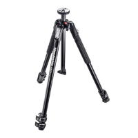
Разработанный для продвинутых любителей и
профессиональных фотографов, чрезвычайно
универсальный штатив идеально подходит для
цифровых и традиционных камер небольшого и
среднего форматов.
ОСНОВНЫЕ ХАРАКТЕРИСТИКИ:
Уникальная подвижная центральная колонна,
которая может использоваться в вертикальной
или горизонтальной плоскостях.
Каждая ножка может быть независимо установ
-
лена под 4 различными углами.
Пузырьковый уровень
Два резиновых утеплителя ножек
Разъем быстрого соединения для подсоедине
-
ния рукояток.
Рычаги Quick Power Lock, позволяющие легко и
одновременно открывать все рычаги.
Крючок для подвешивания противовеса и
крепления ремня.
УСТАНОВКА
и
Откройте 3 ножки штатива.
Для регулировки высоты штатива каждая ножка
имеет систему телескопического удлинения, для
удлинения необходимо повернуть рычаг A на
фиксирующем хомуте “B”.
Возьмите рычага всей ладонью руки. Одновремен
-
но отоприте все фиксирующие рычаги.
БУДЬТЕ АККУРАТНЫ, чтобы не прищемить
палец при открытии рычага (см. рис. 1A)
После достижения необходимой высоты, зафик
-
сируйте “A”.
Регулировка угла ножек
Каждая ножка может быть установлена под 4 раз
-
личными углами. Для изменения угла ножки, слегка
закройте её в направлении центральной колонны
и потяните вниз фиксирующую рукоятку “C”, рас
-
положенную в верхней части ножки.
Удерживая нижнюю часть, выберите новый угол
ножки и отпустите рукоятку “C” для фиксации
положения.
Угол каждой ножки может регулироваться неза
-
висимо от положения двух других ножек.
Последнее положение позволяет достичь уровня
земли.
РЕГУЛИРОВКА
ВЫСОТЫ ЦЕНТРАЛЬНОЙ КОЛОННЫ
Для того чтобы освободить центральную колонну
“D”, отоприте рукоятку “E” и установите колонну
на необходимую высоту. Затяните рукоятку “E” для
фиксации колонны в нужном положении.
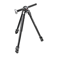
ГОРИЗОНТАЛЬНАЯ ЦЕНТРАЛЬНАЯ КОЛОННА
Подвижная центральная колонна также может
использоваться в горизонтальной плоскости: это
дает возможность не только сдвигать камеру с
положения ножек, но и обеспечивает наиболее
простой способ съемки непосредственно из по
-
ложения над головой:
- отоприте рычаг “E” (4.1)
- нажмите кнопку "Y" и одновременно полностью
поднимите центральную колонну "D", как показано
на рис. 4.2
- нажмите кнопку “Y” и, одновременно, поднимайте
центральную колонну “D” полностью, пока не
покажется красная оболочка, как показано на
рисунке 4.2
- поверните центральную колонну “D” на 90°, как
показано на рисунке 4.3
- передвиньте центральную колонну “D” в отверстие
“W и зафиксируйте рукоятку “E” (рис. 4.4)
ВЕРТИКАЛЬНАЯ ЦЕНТРАЛЬНАЯ КОЛОННА
Для установки центральной колонны в вертикаль-
ное положение, сделайте следующее:
1. отоприте рычаг “E” и полностью вытащите
центральную колонну “D”, как показано на
рисунке 5.1
УБЕРИТЕ РУКИ С ЦЕНТРАЛЬНОЙ КОЛОННЫ
“D” , ЧТОБЫ НЕ ПРИЩЕМИТЬ ПАЛЬЦЫ (см.
рис. 5.2)
2. Убрав одну руку с центральной колонны “D,
другой рукой нажмите кнопку “Y” (5.3)
3. Все еще продолжая работать одной рукой, по
-
верните центральную колонну “D” в вертикаль-
ное положение, как показано на рисунке 5.4
4. Поворачивайте колонну, пока красная стрелка
на оболочке не выровняется со стрелкой на
литье, затем нажмите на колонну.
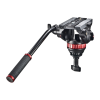
МОНТАЖ И СНЯТИЕ ГОЛОВКИ КАМЕРЫ
Снимите крышку “Z” (рис. 1)
Установите головку камеры на площадку, располо
-
женную на верхней части центральной колонны
при помощи монтажного винта 3/8” (завинчивайте
площадку по часовой стрелке). Затем поднимите
центральную колонну и с помощью маленькой от
-
вертки закрутите винт “M” в основании головки, но
не перетяните его. Эта уникальная характеристика
особенно хорошо работает с головками
Manfrotto, благодаря специально разработанному
основанию, которое не допускает возможность
случайного развинчивания.
Для того чтобы снять головку, расслабьте винт “M” и
отвинтите головку с центральной колонны против
часовой стрелки.
ВЫРАВНИВАНИЕ
и
Штатив оснащен пузырьковым уровнем “H”для
выравнивания штатива.
Пузырьковый уровень можно расположить, как
показано на рисунке 7 для обеспечения максималь
-
ной видимости и удобства.
ВНИМАНИЕ
При использовании штатива вне помещений,
особенно при сильном ветре, можно стабилизиро
-
вать штатив: установите противовес (не входит в
комплект) сверху крючка “L
ПЕРЕВОЗКА
У штатива есть крючок “L для транспортировочного
ремня (опция).
РЕГУЛИРОВКА НАПРЯЖЕНИЯ НОЖЕК
Если ножки с телескопическим удлинением смеща
-
ются даже после фиксации рычага A, необходимо
отрегулировать напряжение фиксации.
Для того чтобы это сделать:
- отпустите рычаг “A”
- поверните винт “P” по часовой стрелке при по
-
мощи специального ключа “N” , расположенного
на одной из ножек штатива.
Как правило, достаточно одной трети поворота для
достижения правильного напряжения фиксации.
КРЕПЛЕНИЕ АКСЕССУАРОВ
Снимите крышку “K”
Штатив оснащен одной внутренней резьбой 3/8”
“X” (рис. 11) , которую можно использовать для кре
-
пления аксессуаров, например, рукояток Manfrotto,
на которые, в свою очередь, можно устанавливать
осветительное оборудование, мониторы и т.д.
1A 1B
2
3
4
5
6
1B 7
8
9
10
11
MT055CXPRO3
170 cm 1,9 kg 9 kg
66.9” 4.2 lbs 19.8 lbs
MT055CXPRO4
170 cm 2 kg 9 kg
66.9” 4.4 lbs 19.8 lbs
MT055XPRO3
170 cm 2,5 kg 9 kg
66.9” 5.5 lbs 19.8 lbs
MT190CXPRO3
160 cm 1,6 kg 7 kg
63” 3,5 lbs 15.4 lbs
MT190CXPRO4
160 cm 1,66 kg 7 kg
63” 3.7 lbs 15.4 lbs
MT190XPRO3
160 cm 2 kg 7 kg
63” 4.4 lbs 15.4 lbs
MT190XPRO4
160 cm 2,05 kg 7 kg
63” 4.5 lbs 15.4 lbs
INSTRUCTIONS
INTRODUCCIÓN
Diseñado para el aficionado avanzado y el
fotógrafo profesional, este es un trípode
extremadamente versátil, ideal para cámaras
pequeñas o de medio formato, digital o tipo
convencional.
CARACTERÍSTICAS CLAVE:
Columna central deslizante única que puede
funcionar tanto en vertical como en el plano
horizontal.
Cada pata puede ser configurada indepen-
dientemente en 4 ángulos.
Nivel de burbuja.
Dos cubiertas térmicas de caucho para las
patas
Conector Easy-Link para fácil inserción de
brazos
Palancas de desbloqueo rápido que pueden
abrirse simultáneamente
Gancho para colgar un contrapeso o una
correa
CONFIGURACIÓN
Y
Abrir las 3 patas del trípode.
Para ajustar la altura del trípode, cada pata
tiene extensions telescópicas que pueden
liberarse abriendo la pinza “A” sobre el collar de
bloqueo “B”.
Sujete las palancas con toda la palma de la
mano. Desbloquéelas todas a la vez.
TENGA CUIDADO de no lastimarse los
dedos al abrir la palanca (véase el dib. 1A).
Cuando se consiga la altura requerida, cierre la
pinza de bloqueo “A”.
AJUSTE DEL ÁNGULO DE LA PATA
Cada pata se puede configurar en 4 ángulos
de apertura.
Para cambiar e lángulo de una pata, junte la
pata hacia el centro de la columna ligeramente
y presione hacia abajo el botón de bloqueo “C”
en la parte superior de la pata. Mientras man-
tiene el botón hacia abajo, seleccione el nuevo
ángulo de la pata y luego libere el botón “C”
para bloquear en posición. El ángulo de cada
pata puede ser ajustado independientemente
de las otras dos patas. La última posición
permite alcanzar el nivel del suelo.
AJUSTE DE LA ALTURA
DE LA COLUMNA CENTRAL
Para liberar la columna central “D”, desbloquee
el pomo “E” y ajuste la altura de la columna
como se desee. Apriete el pomo “E” para
bloquear la columna en posición.
COLUMNA CENTRAL HORIZONTAL
La columna central deslizante puede ser usada
en el plano horizontal: esto no sólo permite a la
cámara estar fuera de la posición de las patas,
sino que proporciona la manera más simple po-
sible de disparar directamente sobre la cabeza:
-desbloquee el pomo “E” (fig. 4.1)
-presione el botón “Y” y, al mismo tiempo,
levante la columna central “D” completamente
hasta que el collarín rojo haya salido (fig. 4.2)
-gire 90° la columna central “D” (fig. 4.3)
- deslice la columna central “D” por el agujero
“W” y bloquee el pomo “E” (fig. 4.4)
COLUMNA CENTRAL VERTICAL
Para configurar la columna central en posición
vertical, proceda como sigue:
1. desbloquee el pomo “E” y tire hacia afuera
completamente la columna centra “D” (fig. 5.1)
PONGA SUS MANOS FUERA DE LA
COLUMNA CENTRAL “D” para
evitar
pellizcarse los dedos (fig. 5.2)
2. mantenga su otra mano fuera de la columna
“D”, presione el botón “Y” con una mano
(fig. 5.3)
3. todavía mantenga la otra mano alejada, con
la misma mano, gire la columna central “D”
en una posición vertical (fig. 5.4)
4. haga rotar la columna hasta que la flecha
roja en el collarín quede alineada con la
flecha en la base, enseguida empuje la
columna hacia abajo
MONTANDO Y
QUITANDO UNA RÓTULA
Quite el tapón “Z” (fig.1)
Monte la rótula en la placa situada en la parte
superior de la columna central utilizando el tor-
nillo 3/8” (atornillando en sentido de las agujas
del reloj). Enseguida, suba la columna central y
con un desarmador pequeño, apriete el tornillo
“M” contra la base de la rótula teniendo cuida-
do de no forzar.
Esta característica única funciona especialmen-
te bien con las rótulas Manfrotto debido a la
base especialmente diseñada para evitar que la
rótula se desatornille accidentalmente.
Para quitar la rótula, afloje el tornillo “M” y
desatornille la rótula de la columna (en sentido
contrario a las agujas del reloj).
Enseguida suba la columna central y con un
desarmador pequeño, apriete el tornillo “M”
contra la base de la rótula teniendo cuidado de
no forzar.
NIVELACIÓN
Y
El trípode tiene un nivel de burbuja“H” que
permite nivelar el trípode.
El nivel de burbuja puede disponerse como se
muestra en la figura 7 para mayor visibilidad y
uso práctico.
NOTA
Para uso en exteriores, especialmente en
condiciones de viento, es posible estabilizar el
trípode: cuelgue un contrapeso (no proporcio-
nado) del anillo “L”.
TRANSPORTE
El trípode tiene un gancho “L”, para una correa
de transporte opcional.
AJUSTE DE LA TENSIÓN
DEL BLOQUEO DE LA PATA
Si las extensions telescópicas de las patas se
deslizan incluso después de haber cerrado la
pinza de bloqueo “A”, será necesario ajustar la
tension de bloqueo.
Para hacer esto:
-libere la pinza de bloqueo “A”
-gire el tornillo “P” en el sentido de las
agujas del reloj usando la llave especial “N”
proporcionada en una de las patas del trípode.
Normalmente un tercio de vuelta sera suficiente
para conseguir la tensión de bloqueo correcta.
MONTAJE DE ACCESORIOS
Quite el tapón “K”
El trípode tiene un agujero roscado de 3/8”
“X” (fig. 11) que se puede usar para montar
accesorios, tales como los brazos Manfrotto
para soporte de luces, monitor etc).
1A 1B
2
3
4
5
6
1B 7
8
9
10
11
Question and Answer IconNeed help?

Do you have a question about the Manfrotto MT055XPRO3 and is the answer not in the manual?

Summary

Manfrotto Tripod Instructions

Tripod Setup

Instructions for opening tripod legs and adjusting height by rotating locking levers.

Leg Angle Adjustment

How to adjust each leg to 4 different angles of spread using the locking button.

Center Column Height Adjustment

Adjusting the center column height by unlocking and tightening knob 'E'.

Horizontal Center Column

Converting the center column to a horizontal position for offset camera shooting.

Vertical Center Column Setup

Setting the center column back to its vertical position, with safety warnings.

Mounting and Removing Camera Head

Instructions for attaching and detaching a camera head using the mounting screw.

Tripod Levelling

Using the integrated spirit level 'H' to ensure the tripod is properly leveled.

Transportation Hook

Description of the hook 'L' for attaching a carrying strap or for optional transport.

Leg Lock Tension Adjustment

Adjusting leg lock tension using screw 'P' to prevent telescopic leg extensions from slipping.

Attaching Accessories

How to attach accessories using the 3/8" female thread 'X' on the tripod.

Overview

The Manfrotto tripod is a versatile and robust support system designed for both advanced hobbyists and professional photographers. It is suitable for use with small, medium format, digital, or conventional cameras, offering stability and flexibility in various shooting scenarios.

Function Description

The primary function of this tripod is to provide a stable platform for cameras, ensuring sharp images and steady video footage. Its design allows for precise adjustments in height, leg angle, and even the orientation of the center column, making it adaptable to a wide range of photographic needs, from standard eye-level shots to overhead or low-angle perspectives.

Usage Features

Setup and Height Adjustment:

To set up the tripod, the three legs are opened. Each leg features telescopic extensions that can be released and locked using lever "A" on the locking collar "B." By grabbing all the levers simultaneously with the whole palm of the hand, all locking levers can be unlocked at once, allowing for quick height adjustments. It is crucial to exercise caution to avoid pinching fingers when opening the levers. Once the desired height is achieved, lever "A" is locked to secure the leg extensions.

Leg Angle Adjustment:

The tripod offers exceptional flexibility with its leg angle adjustment system. Each leg can be independently set at four different angles of spread. To change a leg's angle, the leg is closed slightly towards the center column, and the locking button "C" at the top of the leg is pulled down. While holding the button down, the desired new leg angle is selected, and then button "C" is released to lock it in position. This independent adjustment allows for uneven terrain compensation and enables the tripod to achieve very low floor-level positions.

Center Column Height Adjustment:

The center column "D" can be adjusted for height. To release it, knob "E" is unlocked, allowing the column to be raised or lowered as needed. Once the desired height is reached, knob "E" is tightened to lock the column securely in place.

Horizontal Center Column:

A standout feature of this tripod is its unique ability to convert the center column to a horizontal orientation. This not only allows the camera to be offset from the tripod's legs but also provides an ideal setup for overhead shooting. To achieve this:

  1. Unlock knob "E."
  2. Push button "Y" and simultaneously raise the center column "D" completely until the red shells pop out.
  3. Rotate the center column "D" by 90 degrees.
  4. Slide the center column "D" into the hole "W" and lock it with knob "E."

Vertical Center Column Re-positioning:

To return the center column to its vertical position:

  1. Unlock knob "E" and pull out the center column "D" completely. It is important to keep hands clear of the center column "D" to avoid pinching fingers.
  2. Push button "Y" with one hand.
  3. While keeping the other hand clear, rotate the center column "D" into a vertical position.
  4. Rotate the column until the red arrow on the shells aligns with the arrow on the casting, then push down the column to secure it.

Mounting and Removing a Camera Head:

To mount a camera head, first remove the cap "Z" from the top of the center column. The camera head is then attached to the plate at the top of the center column using the 3/8" mounting screw (screwing clockwise). To secure the head, raise the center column and use a small screwdriver to tighten the screw "M" against the base of the head. Care should be taken not to overtighten. This unique feature, especially when used with Manfrotto heads, prevents accidental unscrewing due to its specially designed base. To remove the head, loosen screw "M" and unscrew the head from the column counter-clockwise.

Levelling:

The tripod is equipped with a spirit level "H" to assist in leveling the tripod. The spirit level can be positioned as shown in the manual to ensure maximum visibility and practicality during setup.

Stabilization for Outdoor Use:

For outdoor use, particularly in windy conditions, the tripod can be further stabilized by hanging a counterweight (not supplied) on the hook "L." This enhances stability and prevents tipping.

Transportation:

The tripod includes a hook "L" which can also be used for attaching an optional carrying strap, making it easier to transport.

Attaching Accessories:

The tripod features a 3/8" female thread "X" (after removing cap "K"). This thread can be used to attach various accessories, such as Manfrotto arms, which in turn can support lights, monitors, or other photographic equipment.

Maintenance Features

Leg Lock Tension Adjustment:

Over time, if the telescopic leg extensions begin to slip even after tightening the locking lever "A," the locking tension may need to be adjusted. To do this:

  1. Release lock lever "A."
  2. Turn the screw "P" clockwise using the special key "N" provided on one of the tripod legs. Typically, a third of a turn should be sufficient to achieve the correct locking tension. This adjustment ensures that the leg sections remain securely locked at the desired height, maintaining the tripod's stability and reliability.

Manfrotto MT055XPRO3 Specifications

General IconGeneral
PurposeDigital/film cameras
MaterialAluminum
Mounting3/8\
Product colorBlack
Number of legs3 leg(s)
Number of leg sections3
Maximum weight capacity8 kg
Weight and Dimensions IconWeight and Dimensions
Weight2500 g
Height (max)1700 mm
Height (min)90 mm

Related product manuals