Do you have a question about the Manfrotto MHXPRO-BHQ2 and is the answer not in the manual?
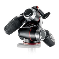
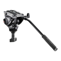
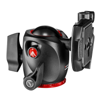
Manfrotto MHXPRO-BHQ2 ball head with load capacity and dimensions.
Attach the ball head to the tripod using the 3/8" thread and set screws.
Screw camera onto plate, align, and ensure secure locking before mounting to head.
Insert the camera plate onto the ball head, ensuring the locking lever engages securely.
Control panoramic and ball movements using levers E and C for positioning and locking.
Adjust ball head friction using knob F for controlled positioning before final locking.
Procedure to safely detach the camera from the ball head using the safety lever.
This document describes the Manfrotto MHXPRO-BHQ2, a professional ball head designed for medium-format cameras, offering precise control and secure mounting for photographic equipment. The ball head features independent movements for both panoramic rotation and ball positioning, providing photographers with versatile adjustments for various shooting scenarios.
The MHXPRO-BHQ2 serves as a crucial interface between a camera and a tripod, enabling flexible camera positioning while maintaining stability. Its primary function is to allow for quick and precise adjustments to the camera's angle and orientation. The head incorporates a quick-release plate system, which facilitates rapid attachment and detachment of the camera. This system is designed with safety mechanisms to prevent accidental camera release, ensuring the equipment remains securely mounted during use.
The ball head's design includes a main ball movement that allows for tilting and panning the camera in almost any direction. This movement is controlled by a locking lever, which, when released, frees the ball for adjustment and, when tightened, securely fixes the camera in the desired position. In addition to the ball movement, the head features an independent panoramic rotation. This allows the camera to be rotated horizontally without affecting the ball's tilt, which is particularly useful for creating panoramic images or making precise horizontal adjustments.
A key feature of this ball head is its separate friction adjustment for the ball movement. This adjustment mechanism allows users to fine-tune the resistance of the ball's movement, making it easier to control the camera's positioning before fully locking it off. By adjusting the friction, photographers can achieve a smoother, more controlled movement, preventing the camera from suddenly dropping or shifting when the main locking lever is released. This feature enhances user control and safety, especially when handling heavier camera setups.
The quick-release plate, designated as "G," is an integral part of the system. It attaches directly to the camera's threaded hole and then slides into the head's receiver. The plate is secured by a locking lever, "H," which engages with the plate to hold it firmly in place. A secondary safety lever, "I," works in conjunction with the main locking lever to provide an additional layer of security, preventing the main lever from opening accidentally. This two-stage locking mechanism is essential for safeguarding valuable camera equipment.
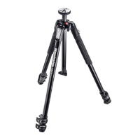
Setting up the MHXPRO-BHQ2 involves assembling it onto a tripod. The head is equipped with a 3/8" female thread ("A") for attachment to most standard tripods. For Manfrotto tripods, there are additional set screws ("B") on the top plate that can be tightened against the base of the head. These screws enhance the locking mechanism, ensuring a more effective and secure connection between the head and the tripod, thereby increasing overall stability.
Attaching the camera to the quick-release plate ("G") is a straightforward process. The camera screw ("M") on the plate is threaded into the camera's base. It is crucial to ensure that this screw is tightened without applying excessive force, and the camera should be aligned with the "LENS" marking on the plate for optimal balance and positioning. Before mounting the camera onto the head, users must verify that the camera is securely fixed to the release plate.
Mounting the camera assembly onto the head involves inserting the quick-release plate ("G") into the head's receiver. This action should be accompanied by an audible click as the main locking lever ("H") engages and closes, indicating that the plate is properly seated. After the click, it is recommended to push the lever "H" again and physically check that the camera is securely fitted to the head, ensuring there is no play or looseness. This step is vital for confirming the camera's stability before use.
Removing the camera from the head requires a specific sequence of actions to disengage the safety mechanisms. First, the camera should be held securely with one hand. Then, the main locking lever ("H") is rotated, and simultaneously, the safety lever ("I") is pushed down. This action allows the main lever to fully open, releasing the quick-release plate and enabling the camera to be lifted off the head. This controlled release mechanism prevents accidental drops and ensures safe handling of the equipment.
The head offers independent control over its panoramic and ball movements. The panoramic movement is locked and unlocked using lever "E." To release the panoramic movement, lever "E" is rotated anticlockwise. Once the desired horizontal position is achieved, turning lever "E" fully clockwise locks the movement. Similarly, the ball movement is controlled by lever "C." To release the ball for positioning, lever "C" is rotated anticlockwise. After adjusting the camera's angle, turning lever "C" fully clockwise locks the ball in place. It is important to always hold the camera with one hand while releasing the ball to prevent sudden movements or drops.
The friction adjustment knob "F" provides an additional layer of control for the ball movement. To adjust friction, the main ball locking lever "C" should be unlocked (rotated anticlockwise). Then, while holding the camera with one hand, knob "F" can be rotated. Turning knob "F" clockwise increases friction, making the ball movement stiffer and more controlled. Turning it anticlockwise reduces friction, allowing for smoother, freer movement. This feature is particularly useful for balancing heavier lenses or achieving precise, slow camera movements. However, it is crucial to remember that friction adjustment does not fully lock the camera; the ball must always be locked by fully turning lever "C" clockwise for secure positioning.
While the manual does not explicitly detail maintenance features, the design of the MHXPRO-BHQ2 implies certain aspects that contribute to its longevity and reliable performance. The robust construction, typical of Manfrotto products, suggests durability under regular use. The use of high-quality materials for the locking levers, quick-release plate, and ball mechanism indicates a design intended to withstand the stresses of professional photography.
The quick-release plate system, with its precise fit and secure locking mechanisms, is designed to minimize wear and tear on both the plate and the head's receiver. Proper engagement and disengagement of the plate, as described in the usage instructions, help preserve the integrity of these components. Avoiding excessive force when attaching the camera to the plate or when operating the locking levers contributes to the longevity of the threads and mechanical parts.
The friction adjustment mechanism, while enhancing usability, also plays a role in maintenance by allowing users to prevent sudden, uncontrolled movements that could potentially stress the internal components of the ball head. Regular, gentle operation of all levers and knobs, as opposed to forceful manipulation, will help maintain their smooth function and prevent premature wear.
Although not explicitly stated, it is generally good practice for photographic equipment to be kept clean and free from dust, sand, and moisture. These elements can ingress into the moving parts of the ball head, potentially causing friction, stiffness, or damage over time. Wiping down the head with a soft, dry cloth after use, especially in challenging environments, can help preserve its operational integrity. Storing the ball head in a protective bag or case when not in use can also shield it from environmental contaminants and physical impacts.
The design of the MHXPRO-BHQ2, with its clear operational steps and safety features, implicitly guides users towards practices that extend the life of the product. By following the instructions for secure mounting, proper locking, and careful release, users can ensure the ball head continues to perform reliably for many years, providing a stable and flexible platform for their photographic endeavors.
| Attachment | Universal \ |
|---|---|
| Product color | Black |
| Lateral tilt angle | -90 - 40 ° |
| Panoramic rotation | 360 ° |
| Maximum weight capacity | 10 kg |
| Height | 115 mm |
|---|---|
| Weight | 500 g |