4 - 8
B - ATTACHMENT WITHOUT HYDRAULICS AND HYDRAULIC
LOCKING DEVICE (OPTION)
MT 523 MONO-ULTRA Série B-E2
MLT 523 Turbo MONO-ULTRA Série B-E2
TAKING UP AN ATTACHMENT
- Ensure that the attachment is in a position facilitating the locking to the carriage. If it is
not correctly oriented, take the necessary precautions in order to move it safely.
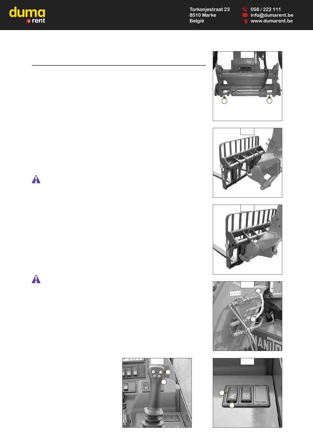
- Check that the rods on the locking cylinder are retracted (fig. A).
- Place the lift truck with the jib lowered in front of and parallel to the attachment, tilt the
carriage forwards (fig. B).
- Bring the carriage under the locking tube of the attachment, slightly lift the jib, incline the
carriage backwards in order to position the attachment (fig. C).
- Lift the attachment off the ground to facilitate locking.
HYDRAULIC LOCKING
- Put the valve in position A (fig. D), that is to say, the hydraulic circuit of the attachment
locking open.
- Press button 1 (fig. E) on the distributor lever to completely lock the attachment to the
carriage.
- Close the valve in position B (fig. D), that is to say, the hydraulic circuit of the attachment
locking closed.
Always close the valve in position B (fig. D) after the locking of the attachment, in order to
avoid accidental unlocking and use the attachment safety.
HYDRAULIC RELEASING
- Put the valve in position A (fig. D), that is to say, the hydraulic circuit of the attachment
locking open.
- Press button 2 (fig. E) on the distributor lever to completely unlock the attachment.
LAYING AN ATTACHMENT
- Proceed in the reverse order of paragraph TAKING UP AN ATTACHMENT while making sure
you place the attachment flat on the ground and in closed position.
INACTIVATE THE HYDRAULIC RELEASE CONTROL
You can change an attachment without leaving the control post, by cutting the electricity
supply to the hydraulic control.
- Leave the valve in position A (fig. D).
- Use switch 3 (fig. F) to cut the electricity supply to the hydraulic control. The circuit is out
of action when indicator 4 (fig. F) is on.
Always cut the electrical power to the circuit using switch 3 (fig. F) after each change of
attachment to avoid involuntary release and use the attachment in complete safety.
E
A
B
C
F
3
4
1
2
D
B
A