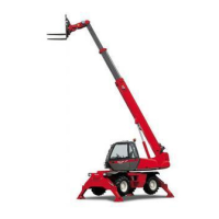
Do you have a question about the Manitou MRT 1432 Turbo M Series and is the answer not in the manual?
| Model | MRT 1432 Turbo M Series |
|---|---|
| Maximum Lift Capacity | 3200 kg |
| Maximum Lift Height | 14 m |
| Engine Power | 75 kW |
| Transmission | Hydrostatic |
| Lift Height | 14 m |
| Fuel Type | Diesel |
| Tyre Type | Pneumatic |
Details about the machine's identification plate.
Information related to the internal combustion engine.
Details regarding the hydrostatic drive system.
Information about the front and rear axles.
Details concerning the operator's cab.
Risks associated with using non-original parts for maintenance.
Services and benefits provided by the manufacturer to the user.
Important warnings and safety advice for the operator.
Risks of operating the machine at excessive speeds.
Core instructions for operating the lift truck safely.
User responsibilities regarding machine maintenance.
Guidelines for understanding load weight and center of gravity.
Procedures for safely picking up loads from the ground.
Safe methods for lifting high loads on tires.
Procedures for safely lowering high loads onto tires.
Safe methods for lifting loads without pallets.
Importance and use of the load status indicator.
Fundamental principles and safety for all maintenance tasks.
Procedures for routine and immediate maintenance tasks.
Guidelines for checking and filling essential fluid levels.
Steps for cleaning the lift truck before or after maintenance.
Overview of machine design for ease of use and maintenance.
Essential pre-start checks for new lift trucks.
Detailed technical specifications of the engine.
Technical data for the hydraulic circuits.
Specifications for the steering system.
Controls exterior lights and horn.
Controls engine ignition and preheating.
Controls service brakes for slowing and stopping.
Engages and disengages the parking brake.
Selects between slow and fast speed ranges.
Procedure to start the heater in continuous heating mode.
Timer for scheduling heating operations.
Location of safety limiter components on the machine.
Panel provides operational info and allows correct settings.
Procedure for starting the machine.
Displays the current operating mode of the machine.
System detects faults in transducers, sensors, cables, or electronics.
MSS system monitors overload and automatically blocks movements.
Key selector for disabling the safety system.
Technical specifications for CM-7 camera.
Technical specifications for CM-8 camera.






 Loading...