4 - 9
D - HYDRAULIC ATTACHMENT AND HYDRAULIC LOCKING DEVICE (OPTION)
MT 732 Série C-E2
MT 732 Turbo Série C-E2
MT 932 Série C-E2
MT 932 Turbo Série C-E2
TAKING UP AN ATTACHMENT
- Ensure that the attachment is in a position facilitating the locking to the carriage. If it is
not correctly oriented, take the necessary precautions in order to move it safely.
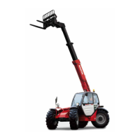
- Check that the rods on the locking cylinder are retracted (fig. A).
- Place the lift truck with the jib lowered in front of and parallel to the attachment, tilt the
carriage forwards (fig. B).
- Bring the carriage under the locking tube of the attachment, slightly lift the jib, incline the
carriage backwards in order to position the attachment (fig. C).
- Lift the attachment off the ground to facilitate locking.
HYDRAULIC LOCKING AND CONNECTING THE ATTACHMENT
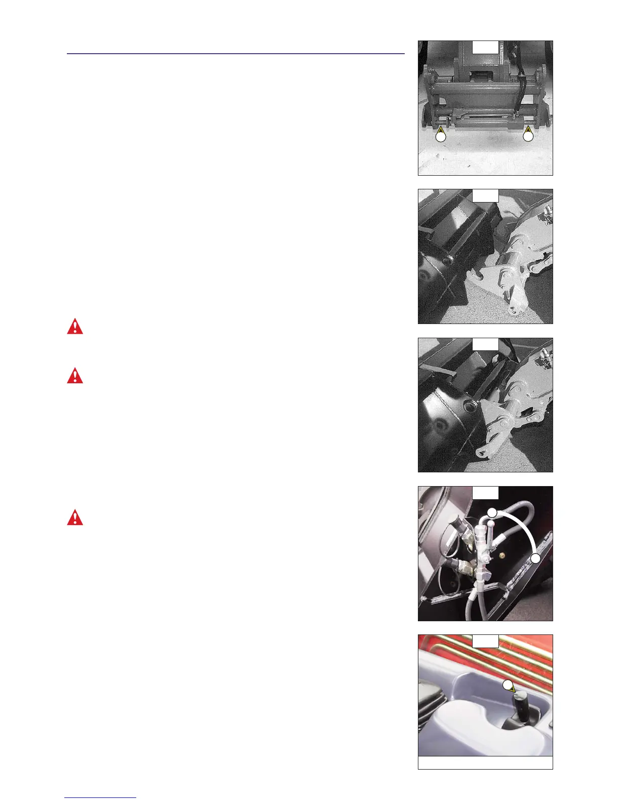
- Put the valve in position A (fig. D), that is to say, the hydraulic circuit of the attachment
locking open.
- Lift up and push the lever of the distributor 1 (fig. E) to the right in order to completely
lock the attachment on the carriage.
- Stop the I.C. engine.
- Remove the pressure of the attachment hydraulic circuit by using the lever of the
distributor 1 (fig. E).
- Connect the rapid connectors according to the logic of the attachment’s hydraulic
movements.
Make sure that the rapid connectors are clean and protect the holes which are not used, with
the caps provided.
- Close the valve in position B (fig. D), that is to say, the hydraulic circuit of the attachment
locking closed.
Always close the valve in position B (fig. D) after the locking of the attachment, in order to avoid
accidental unlocking and use the attachment safety.
HYDRAULIC RELEASING AND DISCONNECTING THE ATTACHMENT
- Close the attachment.
- Put the valve in position A (fig. D), that is to say, the hydraulic circuit of the attachment
locking open.
- Lift up and push the lever of the distributor 1 (fig. E) to the left in order to unlock the
attachment.
- Stop the I.C. engine.
- Remove the pressure of the attachment hydraulic circuit by using the lever of the
distributor 1 (fig. E).
- Disconnect the rapid connectors of the attachment.
Make sure that the rapid connectors are clean and protect the holes which are not used, with
the caps provided.
LAYING AN ATTACHMENT
- Proceed in the reverse order of paragraph TAKING UP AN ATTACHMENT while making sure
you place the attachment flat on the ground and in closed position.
A
B
C
E
D
B
A
1
MT 732 ... / MT 932 ...
 Loading...