NATIONAL CRANE Published 09-06-2019 Control # 691-01 4-27
NBT60L OPERATOR MANUAL SET-UP
in aligning the counterweights. For more information,
see House Lock, page 3-13.
The Counterweight Removal Slew Position Indicator
(yellow arrows) (1, Figure 4-19) appears in the RCL
display, which indicates the rear of the superstructure is
nearly directly above the counterweight stowage area on
the carrier deck.
Ensure vertical alignment of counterweight to the
counterweight mounting lugs on the carrier deck or top
counterweight section to bottom counterweight section
with the optional rear view camera or by leaving the cab
and performing a visual inspection. If necessary, retract
the house lock and rotate the superstructure until
alignment is achieved.
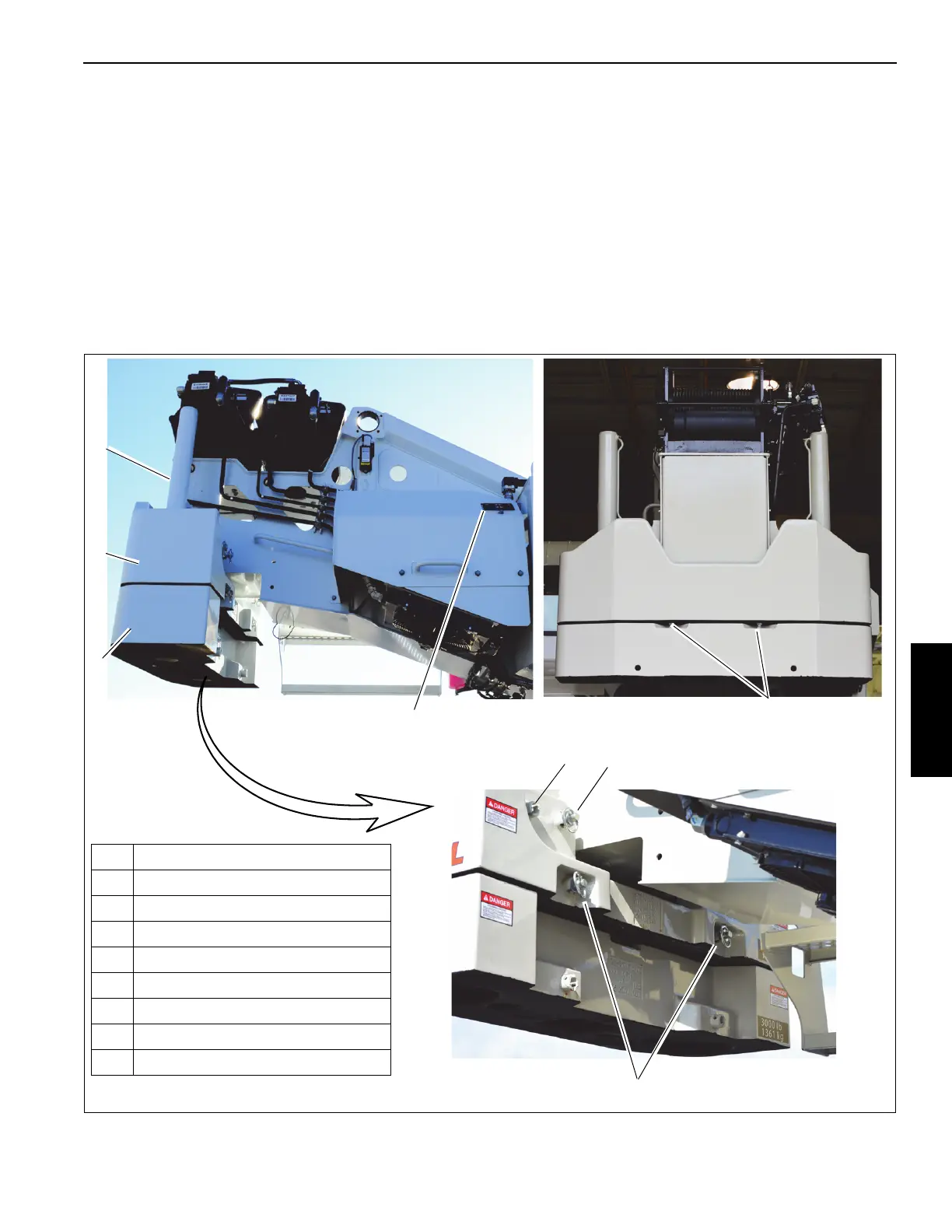
7. If necessary, retract left and right pins (5, Figure 4-20)
from the cylinder on the top counterweight.
8. Remove the left and right pins that secure the bottom
counterweight to the carrier deck.
If the crane is equipped with top and bottom
counterweight sections (1, 2, Figure 4-20) and only the
top section is to be loaded, remove only the left and right
pins (5, Figure 4-20) that secure the top and bottom
sections together. Do not remove pins that secure the
lower counterweights to the carrier deck.
FIGURE 4-20
1 Counterweight Section — Top
2 Counterweight Section — Bottom
3 Removal Cylinders
4 Superstructure Attachment Pin
5 Cylinder Attachment Pin
6 Section Attachment Pin
7 Counterweight Control Panel
8Bolt
9 Jam Nut
1
2
3
4
6
7
9662
5
8
9
9665
(3 Places)
9663

 Loading...


