EasyManua.ls Logo

Manusa SMART SELECTOR WITH LCD User Manual

Manusa SMART SELECTOR WITH LCD
16 pages
Go to English
To Next Page IconTo Next Page
To Previous Page IconTo Previous Page
Page #2 background image
10
DTCXSL02EN - v3
SMART SELECTOR MED LCD-SKÄRM - INSTALLATIONSHANDBOK
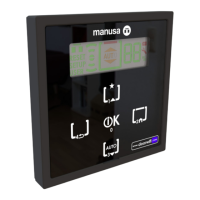
2 - LEDNINGAR TILL DRIVENHETEN (BUS)
En tiometerskabel levereras med väljaren med en kontakt
klar att sättas i och ytterligare en kontakt om du skulle
behöva kapa kabeln. Kapa kabeln så här:
1. Kapa kabeln till önskad längd.
2. Skala av isoleringen enligt nedan och lämna 6 mm (+/- 1
mm) på de fyra ledarna så att det går att sätta på kontak-
3. Kontrollera att ledarna är rena och att de inte har kontakt
med varandra då det kan uppstå kortslutning.
4. Anslut ledarna i kontakterna. Kontrollera polariteten enligt
ritningen nedan och se till att iken på kontakten i ena än-
den vänder mot kabelmärkningen och att iken på motsatta
kontakten vänder mot andra sidan av kabeln.
5. Kläm fast kontakten med klämverktyget
6. Kontrollera att kontakten sitter fast i kabelhöljet och att
metallstiften i kontakten är i kontakt med ledarna.
Koppla in båda ändarna kabeln till RJ-10-kontak-
terna reglagepanelen och väljaren och låt denna
kongurera sig själv att den blir klar för användning.
Under processen kan du eventuellt se meddelandet
”LOADING DATA” under några sekunder på skär-
men.
Tryck på de tre knapparna samtidigt tills meddelandet
”ADDRESS RESET” om inte driftläget visas på skär-
men efter 20 sekunder.
Om en andra väljare ska användas så kan denna
anslutas till RJ-10-kontakten på reglagepanelenveller
något annat tillbehör som redan är inkopplat.
Anmärkning: Koppla inte in den andra väljaren för-
rän den första är i drift!
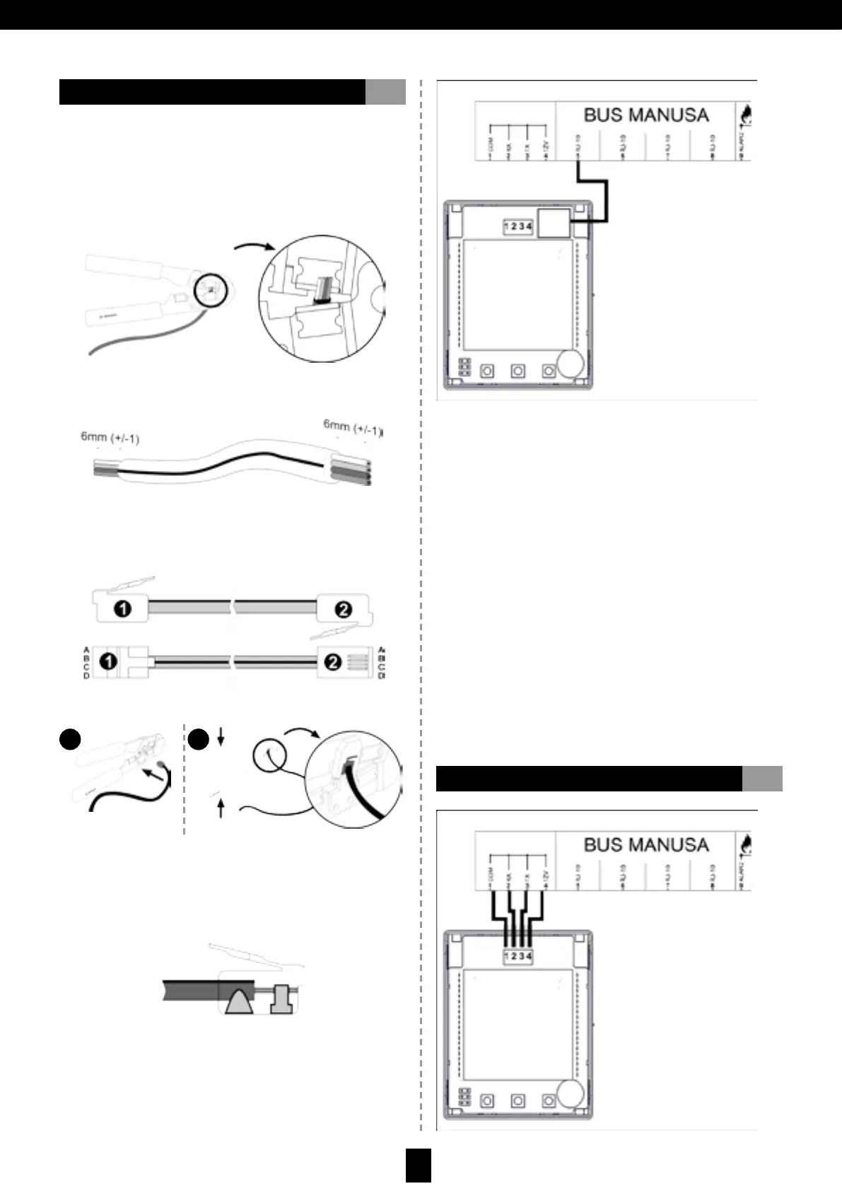
Använd kabeln som levereras med manöverenheten för att
ansluta väljaren till anslutningarna på reglagepanelen.
3 - LEDNINGAR TILL DRIVENHETEN (RELE)
Question and Answer IconNeed help?

Do you have a question about the Manusa SMART SELECTOR WITH LCD and is the answer not in the manual?

Manusa SMART SELECTOR WITH LCD Specifications

General IconGeneral
BrandManusa
ModelSMART SELECTOR WITH LCD
CategoryController
LanguageEnglish

Summary

1. Description

1. LCD display

The primary display for visual feedback on the selector.

2. Message viewing area

Area for displaying operating mode, menus, and alerts.

3. Numeric data area

Area for displaying data like time and cycle counts.

4. Malfunction alerts icon area

Area dedicated to showing malfunction icons.

5. Additional symbols area

Displays operating parameters and selector status.

6. Area of icons

Icons representing the door's operating mode.

7. Confirmation button

Button used to confirm selections and save settings.

8. Right selection button

Button used for navigating options to the right.

9. Left selection button

Button used for navigating options to the left.

2. Wiring to the Drive (BUS)

3. Wiring to the Drive (RELE)

4. Selector Assembly

5. Technical Features

6. Compatibility

7. Selection of the Operating Mode

8. Main Functions

8.1. Keypad Block

Locks the selector keypad to prevent unintended operations.

8.2. PIN Change

Allows the user to modify the Personal Identification Number.

8.3. Reduced Opening

Reduces the door's opening width for specific modes.

8.4. People Counting Sensor

Enables viewing or resetting the people counter.

8.5. Date and Time Management

Allows viewing and adjusting the current date and time.

8.6. Language

Enables selection of the display language.

8.7. Contrast

Adjusts the display contrast for better readability.

9. User Menu

9.1. Menu Navigation

Guides on how to navigate through user menu options.

REDUCED OPENING ACTIVATION

Enables or disables the reduced opening mode for the door.

PIN

Allows the end user to change the Personal Identification Number.

SHOW

Selects what information is displayed in area 3 of the screen.

CLOCK

Option to change the current date and time settings.

LANGUAGE

Allows selection of the display language from multiple options.

COUNTER SETTINGS

Resets people and cycle counters to zero.

CONTRAST

Modifies the screen contrast value.

INSTALLATION

Shows the installation date of the door.

MAINTENANCE

Shows the date of the last technical service or intervention.

CYCLES INST

Shows total cycles since installation date.

CYCLES MAINT.

Shows total cycles since last service.

SELECTOR SOFT

Displays the current software version of the SMART selector.

DOOR SOFT

Displays the current software version of the door's main board.

10. Technical Service Menu

10.1. Menu Navigation

Guides on how to navigate through technical service menu options.

OPENING SPEED

Adjusts the opening speed of each leaf.

CLOSING SPEED

Adjusts the closing speed of each leaf.

CLOSING FORCE

Adjusts the closing force of each leaf.

HOLD OPEN TIME

Sets the time the door leaves stay open.

CLOS COUNTDOWN

Timer to keep lock unblocked before closing.

INS RADAR SENS

Adjusts the sensitivity of the interior radar.

OUT RADAR SENS

Adjusts the sensitivity of the exterior radar.

LANGUAGE

Selects the display language for technical service.

RED OPENING ADJUST

Adjusts the max opening stroke for reduced opening mode.

SELF ADJUSTMENT

Runs the self-adjustment process after installation.

SELECTOR VERSION

Displays the software version of the selector.

DOOR VERSION

Displays the software version of the door's main board.

RESET USR PIN

Resets the user PIN to the factory default value.

11. Safety and Use: Purpose of Use and Uses to be Avoided

12. Reset the Selector Address

13. Malfunctions