1-7
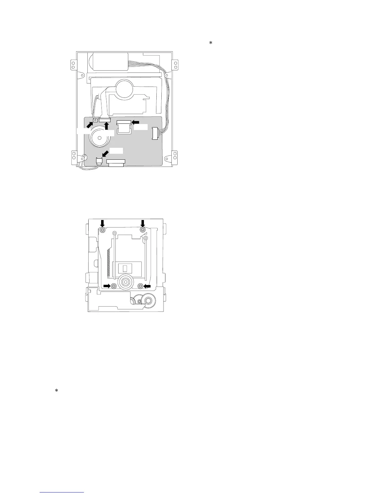
3) Carefully disconnect the two connectors (P500, P600) and
the two flat cables (P200, P300) on the MECHANISM PCB.
Fig. 6-6
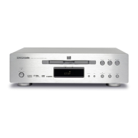
4) Using tweezers, release the four retaining HOOKs of the
TRAVERSE MECHA. from the rubber insulators being
careful not to damage the rubber insulators.
Fig. 6-7
5) Remove the TRAVERSE MECHA. from the MECHANISM
BLOCK.
6) Reassemble in the reverse order for installation. Never
remove the solder on the flexible cable before connecting
the P200 connector on the MECHANISM PCB.
6-2. Replacement of the SPINDLE MOTOR
Because the SPINDLE MOTOR position is very critical, jitter
adjustment should be performed after replacement.
1) Disconnect the P300 connector on the MECHANISM PCB.
2) Insert a Philips type screw driver into the hole on the TURN
TABLE of the SPINDLE MOTOR and remove the two
screws.
6-3. Replacement of the PICK UP BLOCK
Replacement of the PICK UP BLOCK itself is not
recommended because its azimuth adjustment is very
critical and requires a special jig. If PICK UP BLOCK
replacement is necessary, replace with an entire
TRAVERSE MECHANISM only.
P200
P300
P600
P500