4-Stroke Auxiliary Outboard Motor Bracket
Mounting and Operating Instructions
For the following products only:
55-0407AL, 55-0408SS, 55-0410, 55-0416
AUXILIARY OUTBOARD MOTOR BRACKET CAUTION GUIDELINES
1. Always r emove your motor from br acket when tr ailer ing. Failur e to do so may r esult in
damage to boat, motor, or bracket.
2. Do not exceed the stated H.P. rating or weight.
3. Verify that the motor clamps are tight before every use.
4. You must “Always” use a safety cable when operating your motor.
5. Operate motor at low speed. Avoid turning motor at full throttle. Refrain from sharp turns.
6. Operate your motor in lowest position possible for best performance.
7. Raise and tilt motor ONLY when motor is NOT in use or running.
8. Do not alter the motor mounting plate or bracket in any way.
9. Occasional greasing of the pivoting bolts will provide a smoother operation of the bracket.
10. To avoid personal injury, do not contact moving parts and observe all of the above guidelines.
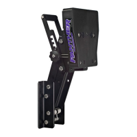
The completed installation should result in the cavitation plate of the outboard motor being two inches
(2”) below the surface of the water. The height of the outboard bracket on the power boat should
be located so that the cavitation plate is 2” below that portion of the bottom of the boat closest to
the engine being mounted. The following instructions should be followed to achieve these re-
sults:
Determine the distance from the outboard motors, clamp screw bracket to the cavita-
tion plate. (See Diagram A). Now subtract 2” from that amount.
After subtracting the 2” from the measured distance, add x inches (get the value of x
from the chart below) to get your TOTAL distance.
55-0407AL & 55-0410 X = 10” 55-0408SS X = 11” 55-0416 X = 16”
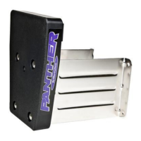
Attach (or tape) a yardstick to the black plastic mounting board of the Panther
bracket, at the previously determined TOTAL distance. (See Diagram B).
(See Diagrams next page) Example: The measurement from the clamp bracket to the cavitation plate of
your outboard is 16 inches in this example. Subtract 2 inches and add the bracket travel from the chart
above (example 1188005 x = 10”). The TOTAL distance is 24 inches (16 -2 +10 = 24”). Therefore, at-
tach the yardstick so the 24 inch mark is even with the top of the Panther black plastic mounting board.
(As per Diagram B). See Next Page
 Loading...