The Mark 7® Power Trim Xpress (model 101-1196) is a specialized reloading tool designed for efficiently trimming brass cases to a precise length, particularly useful for high-volume reloading and cartridge conversion operations. This instruction manual, version 1.1, provides comprehensive guidance on its setup, operation, and maintenance, emphasizing safety precautions throughout.
Function Description
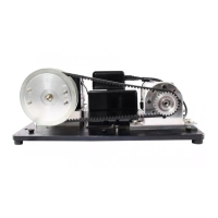
The primary function of the Mark 7® Power Trim Xpress is to trim fired brass cases to a consistent and specified length, which is crucial for safe and accurate reloading. It achieves this by utilizing a brushless trimmer body equipped with a carbide end mill, which precisely cuts the case mouth when the case is run through a trim die installed in a reloading press. The device is particularly adept at converting 223 cases into 300 AAC Blackout in a single pass, highlighting its versatility beyond standard case trimming. The system includes a control box that allows users to adjust the motor speed, enabling optimization for different case materials and trimming requirements to achieve a clean cut and prevent chatter. A key feature for maintaining a clean workspace and efficient operation is the integrated vacuum manifold, which attaches around the trim die and trimmer to evacuate brass chips produced during the trimming process. This manifold is designed to fit standard 1 ½" shop vacuum hoses, ensuring compatibility with common workshop equipment.
Important Technical Specifications
The core components of the Mark 7® Power Trim Xpress system include:
- Brushless Trimmer Body (Item 1): This is the main motor unit that drives the carbide cutter. The brushless design typically implies greater efficiency, longer lifespan, and quieter operation compared to brushed motors.
- Trim Die Adapter (Item 2): Facilitates the connection of the trimmer body to the trim die.
- Socket Head Cap Screws (Item 3): Four M5x0.8mm thread, 10mm long screws are used for securing components, likely the nose cone to the trimmer body.
- Vacuum Manifold (Item 4): A crucial component for chip evacuation, designed to fit 1 ½" hoses.
- 3/8" Carbide End Mill (Item 5): The cutting tool responsible for trimming the brass cases. Carbide is chosen for its hardness and durability, ensuring a long cutting life and precise trims.
- Trimmer Control Box (Item 6): This unit houses the power switch and speed control knob, allowing users to regulate the trimmer's motor speed.
- Power Cord (Item 7): Connects the control box to a power outlet and the trimmer body to the control box.
The trimmer's mounting thread is 13/16"x20, which means that a ¼ turn of the trimmer when adjusting its depth will change the trim length by .0125". This precise adjustment capability is vital for achieving exact case lengths. The control box allows for varying speeds, with a recommended setting of 7-8 for most operations, or adjusted as needed to prevent chatter and ensure a clean cut.
Usage Features
The Mark 7® Power Trim Xpress is designed for integration with a reloading press.
- Installation: The trim die is installed in the press, with considerations for short cases like 300 AAC, which may require the lock ring to be on the underside of the die station or an offset toolhead. The trimmer itself is assembled by first installing the carbide cutter into the collet and tightening it with two wrenches, followed by attaching the nose cone with four screws.
- Setup and Adjustment: After installing the trim die, the press is cycled to bring the shell plate or shell holder to its full travel. The die is then threaded into the press until it contacts the shell plate/holder, backed off about ½ turn. Cases should ideally be sized before trimming for smoother operation and uniform results. A critical step involves using a headspace gauge to verify the setup, adjusting the die deeper or shallower until the headspace is correct, then locking the die body. The trimmer is then threaded onto the trim die until the cutter stops against the case mouth, then backed off about ¼ turn. It is imperative to verify that the carbide cutter does not contact the die body, as this can cause damage. The lock ring must be securely tightened against the trimmer before operation to prevent spinning and potential damage.
- Operation: Once the case length is adjusted, the vacuum manifold is installed around the die and trimmer, secured with two screws, and connected to a shop vacuum. The power cord connects the trimmer to the control box, and the control box to an outlet. The power switch is turned to "On," and the motor speed is set (typically 7-8). Users then run lubed cases through the trim die, checking the overall length and making fine adjustments to the trimmer's position if necessary.
- Cartridge Conversion: The device excels at converting 223 cases to 300 AAC Blackout. During this process, a slower cycle rate and additional dwell time may be beneficial for a clean cut. Users are advised to regularly check the vacuum manifold and hose for chip buildup (every 50-75 cases) and clean them after turning off and unplugging the trimmer. Special attention is required for neck thickness when converting cases, as some 223 cases may produce 300 AAC cases with necks exceeding SAAMI maximum diameter, necessitating selection of specific brass brands.
Maintenance Features
Regular maintenance, particularly regarding the carbide cutter and chip evacuation system, is essential for the longevity and performance of the Mark 7® Power Trim Xpress.
- Cutter Replacement: To change the carbide cutter, the control box must first be unplugged from the power outlet, and the trimmer unplugged from the control box. The trimmer is then unthreaded from the trim die. The four screws holding the mounting adapter to the trimmer motor are removed, and the adapter is lifted off the trimmer shaft. Wrenches are used on the trimmer shaft flats and the collet nut to loosen the collet counterclockwise, allowing the cutter to be slid out. Reinstallation is the reverse of this process.
- Chip Management: The vacuum manifold and hose should be checked frequently (every 50-75 cases during conversion) for chip buildup and cleaned to prevent clogging. This is crucial for maintaining efficient operation and preventing potential damage from accumulated brass chips.
- Safety Warnings: The manual repeatedly emphasizes safety. Users are warned to read and understand all safety and operating instructions, as failure to comply can result in serious injury, illness, or death. Specific warnings include:
- Always verify that the cutter is not touching the die body when adjusting the trimmer, as contact will damage the carbide cutter.
- Always have the lock ring securely tightened against the trimmer before turning it on; a loose lock ring can cause the trimmer to spin and damage the cutter or power cords.
- Turn off and unplug the trimmer before cleaning chips from the vacuum manifold or hose.
For further troubleshooting, users are directed to the knowledge base section on the Mark 7® website under "SUPPORT" and provided with contact information for technical support.