Do you have a question about the Marley 440 Series and is the answer not in the manual?
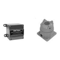
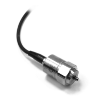
General overview of the vibration switch and its role in protecting machinery from faults.
Details on setpoint controls, time delay, indicators, and operational modes of the switch.
Information on 4-20mA output, solid-state relays, panel settings, and key electrical specifications.
Covers accuracy, environmental limits, enclosure, weight, terminals, and available options.
Instructions for mounting, orientation, temperature considerations, and cable management.
Guidance on wiring to the switch, sealing enclosures, and EMC compatibility.
Details on wiring for triac/analog switches, mechanical relays, and considerations for different load types.
Explanation of operational modes like auto reset, latch, lockout, and safety precautions.
Procedures for setting alarm and shutdown vibration trip levels.
How to adjust the built-in time delay for alarm and shutdown functions.
Using test mode for switch verification and understanding indicator LED behavior.
Internal signal flow from transducer to output, detailing signal processing stages.
Schematic diagrams for fully configured wiring of the vibration switch.