1. Channel A mains power rocker switch
Connects channel A to incoming mains supply.
LED 3 indicates red when activated.
2. Channel A standby switch
Connects channel A's
high voltage circuit to the power supply.
LED 4 indicates green when activated.
Note!
To conserve valve life, standby switch 2 should
remain off for at least 1 minute after powering up the
amplifier.
3/4. Mains & standby LED's.
5. Voice B LED
Indicates red when channel A's voicing
option B is activated.
6. Channel A voice toggle switch
Selects voice
option A or B, this function is repeated on a remote
switching jack on the rear panel (see rear panel
functions). The switch should be in the B position for the
remote switch to be operative.
7. Channel A presence control
Rotary control to
boost the upper mid to high frequency content of sound.
8. Channel A gain control
Rotary control to set and
balance the incoming signal level.
9. Channel B gain control
10. Channel B presence control
11. Channel B voice switch
12. Channel B voice LED
13. Channel B standby LED
14. Channel B mains LED
15. Channel B standby switch
16. Channel B mains switch
Note!
Channel A's notes also apply.
17. Front rack mount fixing holes.
4
A
B
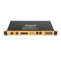
EL34 50/50
Dual MonoBloc Amplifier
1. Mains input socket
Connects amplifier to
incoming mains supply.
2. Channel B mains fuse
Please see specifications for
correct ratings.
3. Channel A mains fuse
Please see specifications for
correct ratings.
4. Channel B H.T. fuse
Please see specifications for
correct ratings.
5. Channel A H.T. fuse
Please see specifications for
correct ratings.
6. Channel B loudspeaker jacks
Connects channel B
to loudspeaker load - model EL34 50/50 - 50 watts RMS,
model EL34 100/100 - 100 watts RMS.
EL34 50/50 & EL34 100/100 Front Panel Features
1 2
3 5 6 7 8 9
10 11
4
12 14 15 16
17
13
Rear Panel Features
MAINS INPUT
120V ~ 60Hz
350 VA
HT FUSE
T315mA
CH B CH A
CH B
LOUDSPEAKER
OUTPUT
CH A
LOUDSPEAKER
OUTPUT
REMOTE VOICE
SWITCHING
(SHORT TO GROUND) USE 'A'
ONLY TO SWITCH BOTH
CHANNELS
CH B CH A
SIGNAL INPUT
USING INPUT 'A' ONLY GIVES DUAL MONO OPERATION (A+B)
WARNING OUTPUT A & B MUST HAVE INDIVIDUAL LOADS IN THIS MODE
CH B CH A
LINK INPUT INPUT LINK
OUTPUT
SELECT Ω
16 8
OUTPUT
SELECT Ω
16 8
WARNING! No user serviceable parts
inside; refer servicing to qualified
personnel only.
AVIS! Risque de choc. Ne pas ouvrir.
WARNING! Fire & Shock Hazard: Do not
expose this unit to rain or moisture. This
Apparatus Must Be Earthed. Do not open
Made in England by:
Marshall Amplification plc, Bletchley, Milton Keynes.
DO NOT USE WITHOUT CONNECTING SPEAKER LOAD SEE MANUAL FOR CORRECT OPERATION AND RATING
EL3450/50
MAINS FUSE
115 V- T3. 15A
230V -T1.6A
CH B CH A
 Loading...