Do you have a question about the Marshall Amplification JCM 2000 TSL100 and is the answer not in the manual?
Crucial safety guidelines for operating the amplifier, covering fuses, servicing, and environmental conditions.
Overview of the TSL series, its features, and the manual's purpose.
Explains what the TSL amplifier can and cannot do, focusing on tone and player technique.
Details on connecting and operating the 5-way footswitch for channel, reverb, and FX loop control.
How to select the Clean channel using front panel switches or footswitch.
Controls input sensitivity for clean to warm breakup tones.
Sets the preamp output level to the power amp.
Modifies EQ by bypassing the Mid control for specific tones.
Passive EQ network to shape the fundamental tone of the amplifier.
Controls in the master section affecting the Clean channel.
How to select the Crunch channel using front panel switches or footswitch.
Provides more gain for aggressive rock and high-gain tones.
Balances the level of the Crunch channel against others.
Reconfigures EQ for a mid-scooped tone.
EQ controls for shaping the distorted signal character.
Master controls shared with the Lead channel.
How to select the Lead channel using front panel switches or footswitch.
Controls and operation for the Lead channel.
Details on additional front panel controls.
Emulates a lower powered amp for reduced output.
Disables output valves for silent recording via DI.
Important rules for valve amplifier power and standby operation.
Socket for connecting the 6-pin DIN footswitch.
Details on the two effects loops and their usage.
Connectors for loudspeakers and impedance selection.
XLR output for PA systems or direct recording.
Power input, fuse locations, protection, and valve types.
Diagrams showing different ways to connect the Line Out to a mixer.
Warns about high voltage presence at output terminals if no loudspeaker is connected.
Diagram of the TSL122 combo front panel for the Clean channel.
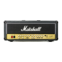
Diagram of the TSL100 head front panel for the Clean channel.
Diagram of the TSL122 combo front panel for the Crunch channel.
Diagram of the TSL100 head front panel for the Crunch channel.
Diagram of the TSL122 combo front panel for the Lead channel.
Diagram of the TSL100 head front panel for the Lead channel.
Diagram of the TSL122 combo rear panel connections.
Diagram of the TSL100 head rear panel connections.
| Power Output | 100 Watts |
|---|---|
| Channels | 3 |
| Power Tubes | 4 x EL34 |
| Reverb | Yes |
| Type | Tube |
| Effects Loop | Yes |
| Footswitch | Yes |
| Speaker Outputs | 2 x 16 Ohm, 1 x 8 Ohm |




 Loading...