RETURNSEND
MAINS INPUT
230V ~ 50Hz
375 WATTS
FUSE
230V - T2AE250V
100-130V - T4AE250V
MODEL:
2555X
1 x 16 OHM
“CLASS 2 WIRING”
CONNECT SPEAKERS BEFORE USE
OUTPUT: 100 WATTS RMS
LOUDSPEAKERS
FX LOOP
1 x 8 OHM
2 x 16 OHM
1 x 4 OHM
2 x 8 OHM
HT FUSE
T1AE250V
FOOTSWITCHD.I.
10. Output Power Switch
This switches power from High Output (100 Watts) to Low Output (50
Watts). The Low Output setting recongures the four output EL34 valves
from Pentode (High) to Triode (Low) mode. Switching from High to Low
not only halves the 2555X’s power output, it also results in a slightly
warmer, less ‘in your face’ tone.
11. Standby Switch
The Standby switch is used in conjunction with the Power switch (item 12)
to ‘warm up’ the amplier before use and to prolong the life of the output
valves. When powering up the amplier always engage the Power switch
rst, leaving the Standby switch on ‘Standby’.
This allows the application of the voltage required to heat the valves to
their correct operating temperature. After approximately two minutes the
valves will have reached the correct operating temperature and the
Standby switch can be engaged.
In order to prolong valve life, the Standby switch alone should be used
to turn the amplier on and off during breaks in performance. Also, when
switching power off, always disengage the Standby switch prior to the
main Power switch.
12. Power Switch
This is the On/Off switch for the mains power to the amplier. When it is
switched on the switch will light red. Please ensure that the amplier is
switched off and unplugged from the mains electricity supply before being
moved.
Front panel functions (cont.)
13. Mains Input
Connects the amplier to the mains power supply.
14. H.T. Fuse
Replace only with the fuse value shown on the panel.
15. FX Loop
Series FX Loop connects the amplier to external FX (approximately
-10dBV level). The Send jack connects to the FX input jack and the Return
jack connects to the FX output jack.
16. Footswitch Jack Socket
Connects remote channel-switching footswitch (supplied).
17. D.I.
Frequency compensated line level output for feeding directly into slave
ampliers or mixing desks.
18. Loudspeaker Output Jacks
There are ve speaker outputs available. They are labelled according to
the intended impedances:
16Ω: connect a 16 Ohm guitar cabinet to this jack.
8Ω: connect a single 8 Ohm guitar cabinet or two 16 Ohm cabinets.
4Ω: connect a single 4 Ohm guitar cabinet or two 8 Ohm guitar cabinets.
WARNING - Although the 2555X amplier has ve speaker outputs, never
attempt to connect more speakers than rated.
The safe combinations are: 1 x 16 Ohm, 1 x 8 Ohm, 1 x 4 Ohm, 2 x16
Ohm or 2 x 8 Ohm. Any other speaker conguration may stress the power
amplier section and in extreme cases may lead to valve and/or output
transformer failure. NEVER use the 2555X without a (speaker) load
attached when the Standby switch is ON.
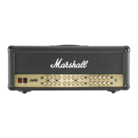
Rear panel functions
131415161718
 Loading...