Fig 3: Squeeze cup lid to gain access to
paper roll
Fig 5: Position of paper roll in printer
Fig 6: Using serrated edge to tear paper
Fig 4: Cut the end off the
paper roll so that the end
has a clean straight edge
MCP9800/UG/E
© MARTEL
INSTRU MENTS
All instruments designed and
manufactured in Great Britain.
The manufacturer reserve the
right to alter specifications
without prior notice
Martel Instruments Limited
Stanelaw Way, Tanfield Lea Industrial Estate, Stanley, Durham DH9 9XG, UK
Tel: +44 (0)1207 290266 Fax: +44 (0)1207 290239
Email: sales@martelinstruments.com
USA Sales Office:
14892 Trojan Circle, Huntington Beach, CA 92647
Tel: (714) 892-0086 Fax: (714) 892-0096
Email: martelusa@earthlink.net
Website:
www.martelinstruments.com
Replacing Paper Roll
If the paper roll needs replacing, open the paper cup lid (squeeze cup lid as shown in Fig. 3) and remove the remaining paper using
the paper feed button, do not pull paper through the printer mechanism. Reel off a few centimetres from a new roll of paper and
check that the end has a clean straight edge (see Fig. 4). Slide the leading edge of the paper through the paper entry slot, with the
leading edge of the paper feeding forwards from the bottom of the roll, until you feel resistance. Press the paper feed button and
feed the paper through the printer mechanism (see Fig. 5). Keep the paper feed button depressed until enough paper is fed through
the printer mechanism to pass through the paper exit slot. Sit the new paper roll in the paper cup and close the lid.
Should the paper become creased or out of line when feeding in a new roll, cut the end off the paper roll, feed out the creased paper
using the Paper Feed button, and reload ensuring the paper has a clean straight edge.
Paper Tear Procedure
When removing printout from the printer, pull the printout toward the front of the printer and tear from one side to the other across the
serrated edge (see Fig. 6).
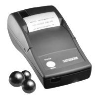
The MCP9800 is a compact and lightweight portable thermal printer with an RS232 serial interface via a 9-way D-type connector.
It is powered from internal Ni-MH batteries and has maintenance free operation, only available with thermal printers. The standard unit is
intended to be trickle charged from a mains power adapter. UK, Euro and US versions of the power adapter are available.
Designed for maximum versatility, the MCP9800 is capable of many different modes of operation with numerous character sets. Operation is
controlled by a combination of switch settings and external software commands.
The MCP9800 is one of a family of thermal printers designed and manufactured in the UK by Martel. All units are built into robust ABS
housings, with a choice of colours. We would be pleased to discuss the possibility of customising any aspect of the printer to specific
requirements.
Specification
Printing system Thermal serial head system
Max characters per line 27
Character matrix 8x6, (8 x 12 double width)
Character size 2.8mm x 1.68mm (approx. 15cpi)
Horizontal dot pitch 0.28mm (Approx. 90dpi)
Vertical dot pitch 0.35mm
Text Line composition 8x116 dots
Printing width 46mm
Average Printing speed Approx. 0.8 lines per second
Dimensions 135mm x 130mm x 64mm
Weight Approx. 350 grammes
Internal power supply 4.8V (600mAH, Ni-MH battery pack)
Paper width 58mm (+0mm -1mm)
Character set UK/United States (437)
Country codes USA, France, Germany, UK, Denmark I/II,
Sweden, Italy, Spain & Japan
Interface
Input data format 8 bit serial RS232C (1 Stop Bit, No Parity)
Connector 9-way D-type socket
Baud rates 1200, 2400, 4800 & 9600
Handshaking Hardware (CTS line) or Software (XON/XOFF)
Environmental Conditions
Operating range 0
o
C to +50
o
C
Storage range -40
o
C to +60
o
C
Charging range +10
o
C to +45
o
C
MTBF 500,000 lines
Fig 1: Pin Numbers for
Serial Interface Connector
Serial Interface
T
he RS232 standard is used, and the baud rate is selectable from
1200, 2400, 4800 and 9600 bits per second via the DIP switches.
110, 300, 600 and 19200 baud rates can be made available as an
option.
The printer is fitted with a 9-way D-type socket (Fig 1 illustrates the
pin numbers for the connector), the pin assignments and interface
signals are defined below.
PIN Signal I/0 Definition
1 n/c N/A No connection
2 TxD 0 Transmitted data to host
3 RxD I Received data from host
4 n/c N/A No connection
5 GND N/A Signal ground
6 n/c N/A No connection
7 n/c N/A No connection
8 CTS 0 Clear to send
9 n/c N/A No connection
MCP9800
THERMAL PRINTER
User Guide
Stanelaw Way
Tanfield Lea Industrial Estate
Stanley, Durham DH9 9XG, UK
Tel: +44 (0)1207 290266
Fax: +44 (0)1207 290239
Email: sales@martelinstruments.com
Features
•
High print quality
•
Quiet, non-impact system
•
Maintenance-free
•
Compact and lightweight
•
High reliability
•
Battery powered
•
Versatile, for use with text or graphics
9 —— 6
5 —— 1