Do you have a question about the Martin DC3700 and is the answer not in the manual?
Introduces the Martin DC3700/DC2500 garage door opener system and its capabilities.
Details specifications for DC3700 and DC2500 models, including door height limits.
Provides initial guidance on door brands, mounting types, and safety instructions.
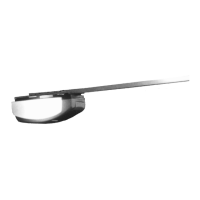
Illustrates components and mounting for side-mounted garage door openers.
Specifies that this installation is for Martin Finger Shield Garage Door Systems only.
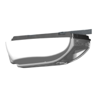
Illustrates components and mounting for center-mounted garage door openers.
Notes that center mount openers may be mounted off-center for specific installations.
Lists items included in the power head box for both DC3700 and DC2500 models.
Details the components found within the rail assembly box.
Lists various screws, brackets, and other hardware provided with the opener.
Covers safety, door balance, lock disabling, and control placement for installation.
Provides essential monthly checks, operating safety, child safety, and emergency release usage.
Lists helpful tools and materials needed for a satisfactory garage door opener installation.
Warns against using center mount designs on other brand doors to avoid binding and failure.
Explains how to fasten the opener power arm outside the opener door bracket for side mounting.
Details fastening the opener power arm inside the opener door bracket for center or off-center mounting.
Provides specific adjustments for 8", 2.5", and 4.25" low clearance track installations.
Details fastening the opener door bracket to the door and connecting the power arm.
Explains how to mark and fasten the opener header bracket to the header beam.
Describes attaching the rail assembly to the power head chassis using "C" brackets.
Details securing the rail assembly end-stop to the opener header bracket with a clevis pin.
Guides raising the opener and securing the rail assembly to the ceiling.
Explains twisting, sliding, and fastening the rail support bracket for stability.
Instructions for inserting light bulbs and snapping light lenses into the power head.
Covers mounting photo eyes directly to the wall or using brackets for safety.
Details routing and connecting photo eye wires to the power head chassis terminals.
Explains mounting the wall control and connecting its wires to the opener.
Covers removing tape, positioning, and fastening the straight and curved power arms.
Explains how to use the emergency release cord to connect/disconnect the trolley.
Instructions for plugging in the opener and optional permanent wiring safety.
Introduces the Martin "Smart Computer" control panel and its buttons/LEDs.
How to enter programming mode using the "P" button.
Adjusting the door's fully open position using "+" and "-" buttons.
Adjusting the door's fully closed position using "+" and "-" buttons.
Adjusting the force required to open the door based on door size.
Adjusting the force required to close the door based on door size.
Pairing a transmitter with the opener by transferring its code.
Completing programming by running the door through full cycles to set memory.
Verifying the door stops and reverses upon contact with an object.
Checking if the door reverses when the photo eye beam is interrupted.
Instructions for applying important safety and warning labels inside the garage.
Guidance on accessing and replacing the transmitter's battery.
Describes various ways to mount or carry the transmitter.
Steps for cloning codes from a present transmitter to a new one.
How to use the transmitter to open, close, or stop the garage door.
Instructions for positioning the antenna wire to optimize signal range.
How to operate the door, use vacation lock, and control opener lights via the wall control.
Procedures for checking and increasing/decreasing belt or chain tension.
Guides for measuring, cutting, and reassembling the rail assembly to shorten it.
Detailed list and diagram of parts for the DC3700 power head assembly.
Lists and illustrates components of the DC3700 belt rail assembly.
Lists and illustrates components of the DC2500 chain rail assembly.
Diagnoses and solutions for when the opener doesn't respond to controls.
Addresses problems like incomplete opening/closing and unexpected reversal.
Solutions for when opener lights don't illuminate, turn off, or power fails.
Solutions for openers straining, needing maximum force, or not moving the door.
Explains the meaning of various LED illuminations and blinks on the control panel.
Provides solutions for specific problems indicated by LED codes for service technicians.
Lists common areas on garage doors that pose a high risk of serious injury.
Details common severe injuries associated with high-risk garage door features.
Illustrates and identifies high-risk components in sectional garage doors.
Illustrates and identifies high-risk components in one-piece garage doors.
| Brand | Martin |
|---|---|
| Model | DC3700 |
| Category | Garage Door Opener |
| Language | English |