Do you have a question about the Masibus 5002U-P and is the answer not in the manual?
Basic manual intro, notices on updates, and product/third-party trademarks.
Guide to checking package contents and product ordering codes.
Lists included accessories and provides crucial safety information.
Explains warning and caution symbols used in the manual.
Describes the process and location requirements for controller installation.
Provides physical dimensions and panel mounting specifications.
Details the wiring procedures and necessary precautions.
Details input types, ranges, and accuracy.
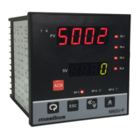
Describes the front panel display and operational buttons.
Outlines the controller's output types and their specifications.
Specifies relay configuration, rating, mode, and loop power supply.
Covers communication, power, and physical dimensions/materials.
Details environmental conditions and unique product functionalities.
Illustrates the electrical connections on the controller's back plate.
Shows the wiring diagram for the transmitted power supply.
Describes the PV/SV displays and status indicator lamps.
Explains the function of each key on the front panel.
Parameters viewable or changeable during runtime operation.
Guide on how to set the controller's set point value.
Configuration of alarm settings for Level 1 parameters.
Configuration of functional parameters for Level 2.
Details functional parameters for Level 2, Part 1.
Details functional parameters for Level 3, Part 2.
Continues the details for Level 3 functional parameters.
Details the calibration procedure for various input and output parameters.
Describes the factory reset procedure and its effects on parameters.
Describes the five configurable settings available for each alarm.
Lists various alarm types with display messages and operational notes.
Illustrates different alarm types and explains hysteresis behavior.
Explains the direction setting and delay function for alarm relays.
Explains proportional control logic for heat/cool actions.
Details the proportional band setting for effective process control.
Describes the manual reset adjustment for output control.
Explains the cycle time setting for PI, PD, PID control actions.
Details the programmable low pass filter for process value stability.
Procedure for calibrating ambient temperature compensation.
Steps for calibrating PV input for TC, Linear, and RTD types.
Procedure for calibrating voltage/current outputs.
Lists Modbus function codes and their operational purposes.
Explains Modbus exception codes and their respective meanings.
Lists Modbus parameters for PV and Ambient readings.
Lists Modbus parameters for Set Point, Alarms, and other settings.
Continues the list of Modbus configurable parameters.
Provides a flowchart for diagnosing common instrument operational issues.
Shows display messages for various input burnout conditions.
Details retransmission output behavior during OPEN/OVER/UNDER conditions.
Explains how to select current or voltage output type.
Describes the logic for relay behavior under various alarm and control conditions.
| Brand | Masibus |
|---|---|
| Model | 5002U-P |
| Category | Temperature Controller |
| Language | English |