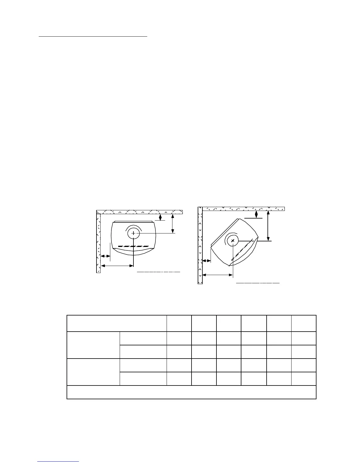
POSITIONING YOUR HEATER
The heater must not be installed under a heat sensitive ceiling of less than normal height
(approx. 2.4 metres). No wall or other immovable object may be closer to the front of
the heater than one metre. The heater may be installed in front of, or partially into a
fireplace which has a suitable heat resistant surround, but any heat sensitive material
(such as a mantel-piece) which protrudes from the face of the fireplace surround will
need to be completely shielded. This shielding is best provided by a sheet metal panel
held 12mm from the face to be protected on heat resistant spacers. The inner edge of
the shield must abut the face of the fireplace surround and the outer edge and ends must
have an unobstructed 10mm gap to allow cooling air circulation. Floor protection, to
the extent shown below, must be provided either by the existing hearth or by an
extension to it. Any extension must be securely fixed and must fit snugly against the
hearth so that there is no gap which might allow a small ember to reach the floor
beneath. (See INSTALLING THE FLUE for the flue requirements for a fireplace
installation)
Finalise the installation position for your woodfire only after considering the necessary
heater-to-wall distances (see below) and checking the practicability of installing the flue
system through the ceiling and roof or wall. As a guide, the flue shielding and the
25mm clearance gap around it in the ceiling space will occupy a diameter of
approximately 300mm, and this must be available without the removal of structural
beams.
If a ‘through-the-wall’ flue system is contemplated, consult AS 2918 or NZS 7421 for
the appropriate wall constructional requirements and verify that these will be feasible
for your existing wall structure.
B
D
A
C
Parallel Inst allation
.
E
E
F
F
Corner Inst allation
MINIMUM DISTANCES (mm) TO HEAT SENSITIVE WALLS WHEN
THE REAR SHIELD AND A FLUE HEAT SHIELD ARE FITTED
A B C D E F
Australia Arcadia 200 575 350 838 450 700
Utopia Ser. 2 300# 500* 455# 808 350*§ 650§
New Zealand Arcadia 300 512 450 775 350 600
Utopia 345 642* 500 950 350* 650
See next page for recommended Australian flue options
#
Reduce by 50mm if the flue heat deflector is polished stainless steel.
*
These dimensions are measured from the edge of any side-fitted warming shelf. In this
case, dimensions D and F will increase accordingly.
§
Increase by 50mm if no flue heat deflector is fitted.
4