GB
DANE TECHNICZNE
MODEL AC 1000 E AC 1200 E
Cooling capacity
10000 BTU/h
2930 W
12000 BTU/h
3516 W
Power/Ampere consumption for cooling 1137 W / 5,2A 1325 W / 6,3 A
Air volume (max. speed) 480 m
3
/h 480 m
3
/h
Humidity removal capacity 1.2 l/h 2.0 l/h
Power supply 220-240V~. 50Hz
Compressor Rotary
Refrigerant R410A (Please refer to rhe rating labe.)
Fan speed 3
Timer 1~24 hours
Working temperature 18 ~ 32
o
C
Exhaust pipe Ø 142x1500mm
Net Weight 27,5 kg 29,5 kg
Dimension 422x443x825 mm (WxDxH)
REMARK:
1. Measuring condition for above is as per EN 14511 : DB=35°C , WB=24°C
*DB = temperature of dry bulb = room temperature, WB = temperature of wet bulb = relative humidity.
2. Test condition for data in our rating label is as per safety regulation: EN 60335-2-40
3. Current & Fuse : F2L250V or T2L250V
4. The appliance AC 1200E series can be connected only to a supply with system impedance no more than 0.289Ω. In case necessary, please
consult your supply authority for system impedance information. "
BEFORE USE
GENERAL SAFETY
• Only use in the upright position on a flat level surface and
at least 36cm from any objects (fig 1 & 4).
• Do not place objects on the unit or block the air inlet /
outlet (fig. 2).
• Closely supervise any children and pets when the unit is in
use.
• This appliance is not intended for use by persons
(including children) with reduced physical, sensory or
mental capabilities, or lack of experience and knowledge,
unless they have been given supervision or instruction
concerning use of the appliance by a person responsible for
their safety. Children should be supervised to ensure that
they do not play with appliance.
ELECTRICAL SAFETY
• For indoor use only.
• Switch off and unplug when not in use.
• Do not use in humid or wet environments (Fig 3)
• Do not pull the unit along by the cord.
• IF THE SUPPLY CORD IS DAMAGED, IT MUST BE
REPLACED BY AN ELECTRICIAN OR SIMILARLY
QUALIFIED PERSON, TO AVOID HAZARD.
FOR MAXIMUM EFFICENCY
• Close doors and windows
• Keep curtains of blinds closed during the sunniest part of
the day
• Keep filters clean
• Once room has reached the desired conditions, reduce
temperature and ventilation setting
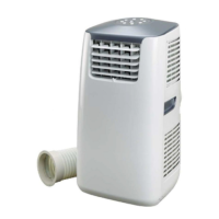
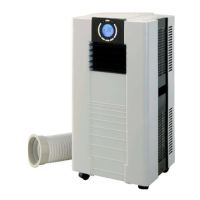
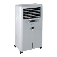
PARTS
Front (Fig. 5)
1. Control Panel
2. Carrying handle
3. Water tank
4. Caster
5. Air outlet
Back (Fig. 6)
6. Air filter
7. Exhaust air outlet
8. Air filter
9. Air inlet
10. Cord storage
11. Air inlet
12. Water stopper / drainage point
Accessories (Fig. 7)
13. Exhaust hose.
14. Adaptor - for insertion over hose and into window spacer
(or into hole in the wall/window).
15. Cover for adaptor
16. Window spacer - for filling the open window space
17. Window spacer - for filling the open window space
18. Window spacer - for filling the open window space and
with hole for connection to exhaust hose.
19. Drain tube for continuous drainage
20. Active carbon filter
21. Remote control