EN
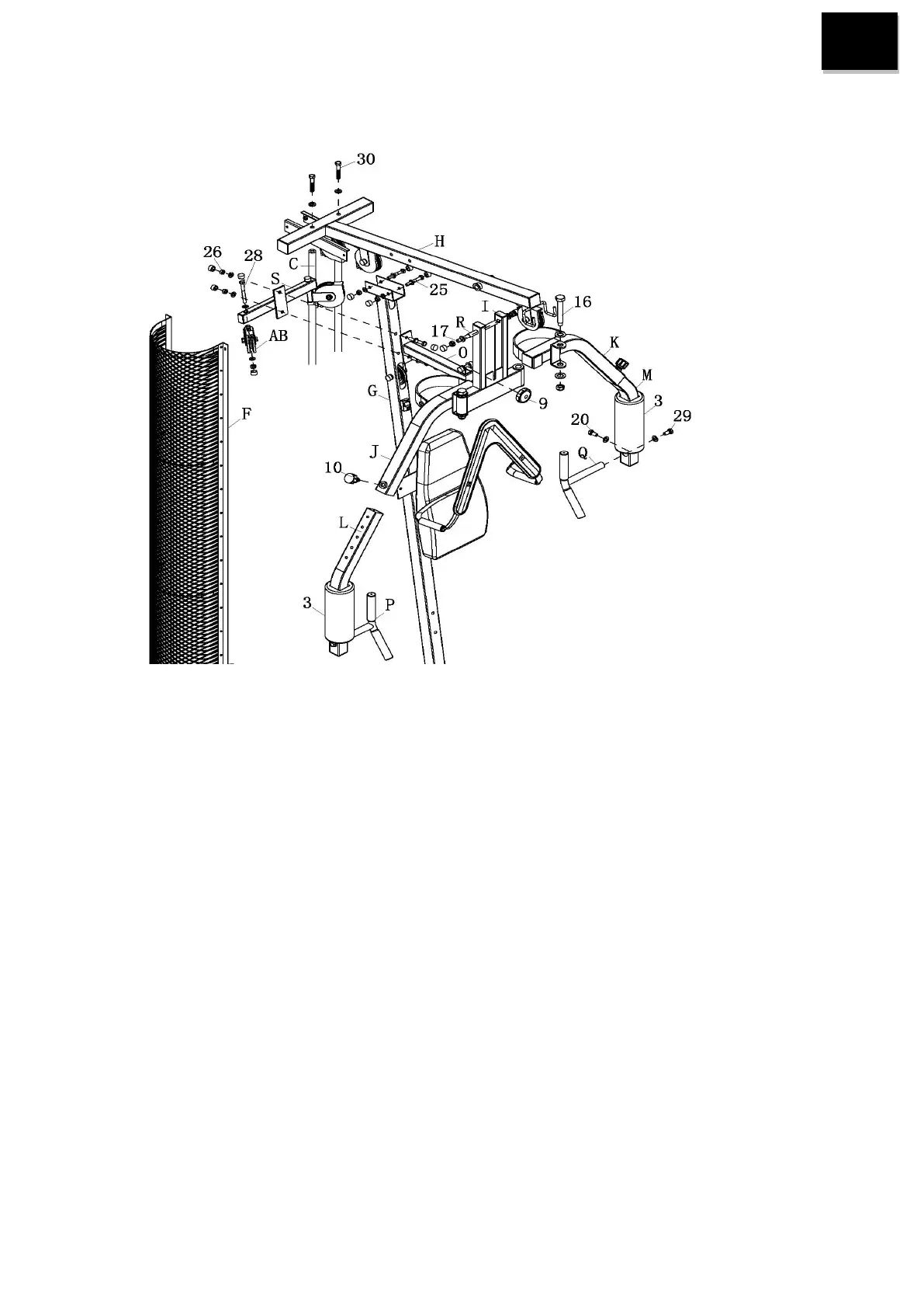
STEP 3
1. Attach top cross beam (H) to main frame (G) and guide rod(C) with bolts M10*70+washers+nuts (25) and
bolts M12*70+washers (30).
2. Attach resist bar (O) and pulley block support (S) to main frame (G) with bolts M10*75 washers + nuts
(26).
3. Attach pulley block (AB) to pulley block support (S) with bolts M10*110+washers+lock nuts (28).
4. Attach press bar (I) to top cross beam (H) with joint tube (R) and bolt M12*155+washers+lock nuts (17).
5. Attach up right & left chest support (J&K) to press bar (I) with big bolts %%c19+washers+lock nut M16
(16).
6. Insert down right & left chest support (M&L) into up right & left chest support (J&K) screw with fast pin
(10).
7. Attach right & left hand grip (P&Q) to down right & left chest support (M&L) with bolts
M12*20+washers (29) and bolts M8*20+washers (20).
8. Attach shells (F) to back base (B) and top cross beam (H) with bolts M6*16 (18).