R
www.mastermotion.eu
433,42 MHz
rev00_ 23.06.17
User manual:
24
Dear Customer, thank you for purchasing a
MASTER S.p.A. product. This guide contains all the
information you will need concerning the use of this
product. Read the instructions carefully and keep
them for further consultation. The receiver module
MIR 24 is specially designed for the control of a DC
electric motor with mechanical limit switches. All
other use beyond the field defined by MASTER
S.p.A. is forbidden. This, as well as the breach of the
instructions given in this guide, shall release
MASTER S.p.A. from any liability and shall annul
the product warranty.
All products and technical specifications given in this document are subject to variation without notice. The manufacturer shall not
be liable for damage resulting from improper, incorrect or unreasonable use.
ü n° 1 MIR 24
ü n° 1 wall bracket
ü this manual
Package contents
ü Check that the package is intact and has not been damaged in transit.
ü The product is designed to be inserted inside of junction boxes. The module does not provide any
protection against water and only essential protection for contact with solids.
ü It is forbidden to install the module in areas not adequately protected, and near sources of heat.
ü Use momentary (hold-to-run) control buttons. Do NOT use stay-put switches.
ü Position the buttons within sight of the roller shutter/awning but a long way from its moving parts.
Position the buttons more than 1.5 m from the floor.
ü Install the product carefully, using suitable tools.
ü If there are several radio appliances in the same system, they must not be less than 1.5 m apart.
ü Do not install the product near metal surfaces.
ü Do not modify or replace parts without the manufacturer's permission. Do not pierce or tamper the box.
ü The antenna cable carries line voltage. Do not cut the antenna cable as this would be dangerous. If the
antenna cable is damaged, replace the product.
01B. WARNINGS FOR INSTALLATION
At the end of the product life cycle,
dis pos e of the device in
compliance with local regulations.
This product could contain
substances that are harmful to
h u m a n h e a l t h a n d t h e
environment: do not dispose of the
product in domestic waste.
Disposal
ü Power supply: 24 Vdc
ü Contact capacity: 2A
ü Dimensions: 45 x 38 x 25 mm
ü Weight: 40 gr
ü Operating temperature: from -20 to +55°C
ü IP protection: IP20
ü Operating time: adjustable from 5 to 240 sec
ü Frequency: 433.42 MHz
ü Memorizable transmitter: 15*
ü Memorizable wind sensor: 4
ü Range (estimes): 100 m outdoor, 20 m indoor
(*) rain sensor and sun sensor included
Technical specifications
Do not use radio systems in places with strong interference (for example, near police stations, airports,
banks, hospitals). It is in any case advisable to carry out a technical inspection prior to installing any radio
system in order to identify possible sources of interference.
Radio systems can be used where any disturbances or malfunction of the transmitter or receiver do not
constitute a risk factor, or if such factor is eliminated using appropriate safety systems.
The presence of radio devices working at the same transmission frequency (433.42 MHz) may interfere
with the radio receiver and reduce the range of the system, limiting functionality.
Notes on radio systems
ü The product is not intended for use by persons (including children) with reduced physical, sensory
or mental capabilities, or lack of experience and knowledge, unless they are supervised or given
instructions on how to use the product by a person responsible for their safety.
ü Before operating the roller shutter/awning, make sure there are no people or objects in the area
involved in its movement. Check the automation during movement and keep people at a safe
distance, until the movement ends.
ü Do not allow children to play with the appliance or with the fixed control devices. Also, keep the
portable control devices (remote controls) out of the reach of children.
ü Do not operate the roller shutter/awning when maintenance operations are being carried out (e.g.
window cleaning). If the control device is automatic, disconnect the motor from the power line.
01C. WARNINGS FOR USE
02. ELECTRICAL CONNECTION
ü Make the connections with the power switched off.
ü Check that the power line does not come from electrical circuits intended for lighting.
ü A circuit breaker or residual current device must be inserted in the power line. An isolating device with
overvoltage category III, namely distance between contacts of at least 3.5 mm, must be inserted in the
power line
ü The product has no protection against overloads or short circuits. Install a protective device in the power
line that is appropriate for the load, such as a fuse of max. 2 A.
ü You can not connect more than one motor directly to the module.
ü Use momentary (hold-to-run) control buttons. Do NOT use stay-put switches. The control buttons are
connected to the line voltage and must therefore be properly isolated and protected.
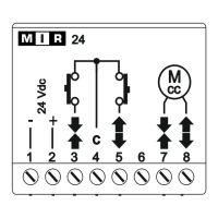
Power supply
The module must be powered at 24Vdc. The supply voltage must be applied to terminals 1 (-) and 2 (+).
Connecting the motor
The motor windings must be connected to the terminals 7 and 8. You can not connect more than one
motor directly to the module. For each module you can connect only a single DC motor.
Connecting the command buttons (optional)
The buttons must be connected to terminals 3 and 5, the common thread of the buttons must be
connected to terminal 4. You must use momentary (hold-to-run)control buttons, do not use buttons
with maintained position. More than one command button can be connected to the unit through a parallel
connection. To make an up or down movement, press the button for at least 0.5 seconds; to stop the
operation briefly press any of the buttons.
NOTE: This product is compatible with
Arco, Visio, Flute, Kuadro, Kort and
equivalent transmitters.
Before starting the programming procedure, read
the instruction manual of the transmitter.
In the following description the transmitter is
represented in a generic way.
ü Incorrect installation can cause serious injuries.
ü Keep these instructions for future maintenance work and disposal of the product.
ü All the product installation, connection, programming and maintenance operations must be carried out
only by a qualified and skilled technician, who must comply with laws, provisions, local regulations and
the instructions given in this manual.
ü The wiring must comply with current IEC standards.
ü Some applications require hold-to-run operation and can exclude the use of radio controls or require
particular safety devices.
ü To prevent potentially dangerous situations, check the operating condition of the roller shutter/awning
regularly.
01A. WARNINGS FOR SAFETY
01. WARNINGS!
01. Warnings
02. Electrical connection
03. First installation
04. Memorization/deletion of radio device
05. Operating logic of wind sensor
06. Operating logic of sun sensor
07. Operating logic of rain sensor
08. «Air Change» function
09. Orientation function
10. Working time
11. Buttons logic
12. RESET
Index
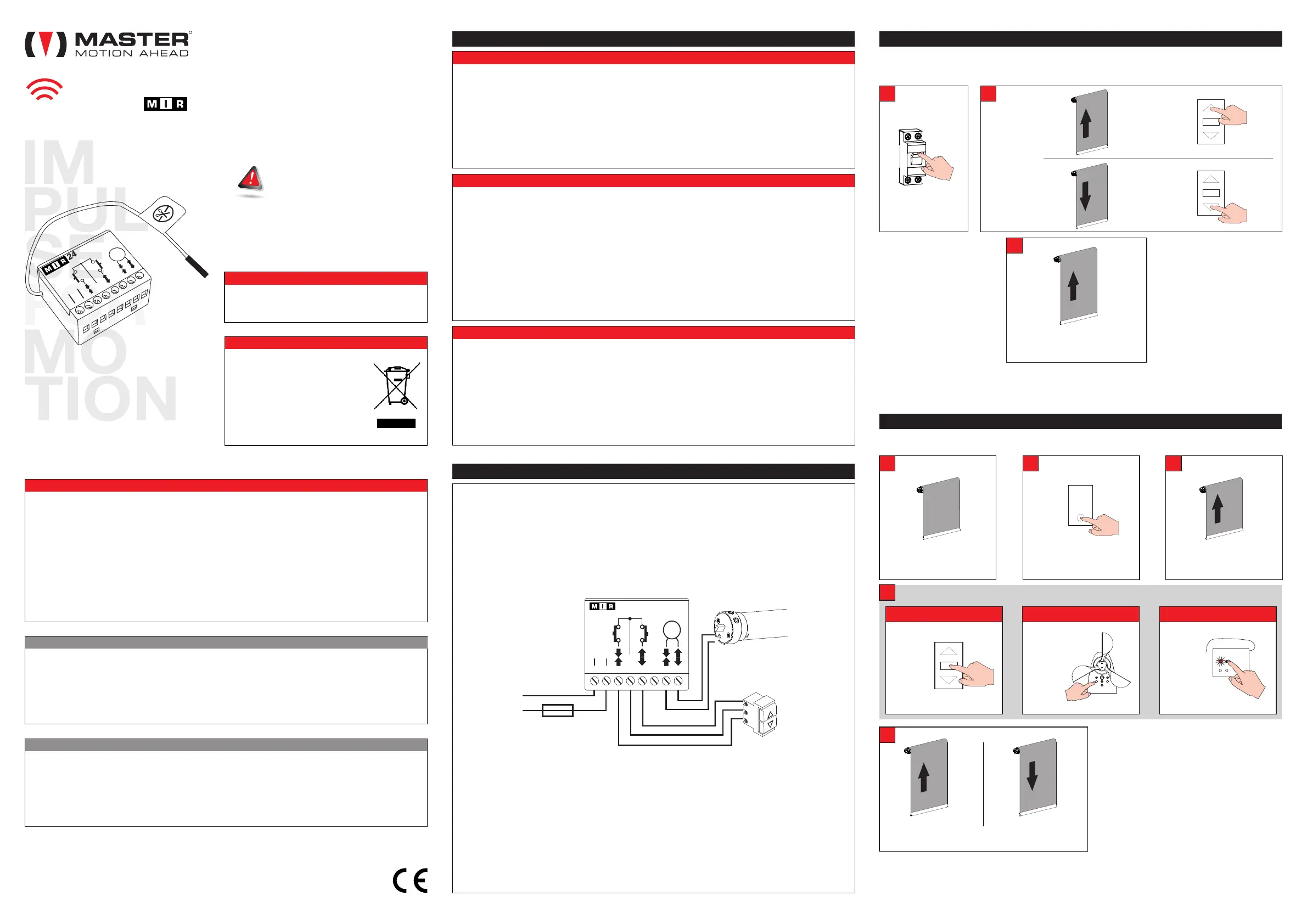
This procedure is used to memorize the first transmitter.
Warning: before starting the installation procedure, adjust the mechanical
limit switches of the motor connected to the module.
03. FIRST INSTALLATION
In the event that the installation is not successful, you can restore your system to factory condition (see
section 12. RESET).
ON
Supply the module
A
The motor
makes 4
movements...
B
C
within 15s press
x4
within 15s press
The motor makes a brief upward
movement
IF
IF
x4
UP
DOWN
x1
With this procedure you can store / delete others transmitters in addition to the first already stored, or store
/ delete wind sensor or a sun/wind sensor or store / delete a rain sensor.
ü The module can store up to 15 radio codes
(excluding sensors, wind or sun / wind radio).
The "out of memory" condition is indicated
with two downward movements.
ü If the motor has stored a single hand-held
transmitter, it can't be deleted (the non-
cancellation is indicated by two downward
movements).
ü The module can store up to 4 wind radio
sensor, one of which may be a sun sensor /
wind. The "out of memory" condition is
indicated with two downward movements.
ü The module can store more rain sensors.
ü If the sensor is a battery sensor button 1
must be pressed up to 10 seconds.
Bring the motor to an
intermediate position
A
The motor signals the operation performed
MEMORIZED !
DELETED !
E
Press for 5 seconds the
PROG button of a transmitter
already memorized.
B
The motor makes 2 upward
movements
C
WIND SENSOR
(1)
RAIN SENSOR
P2
(1)
(1)
Hand-held TRANSMITTER
D
WITHIN 15 SECONDS PRESS:
(1)
STOP
P1 P2
x2
x1 x1
04. MEMORIZATION / DELETION OF A RADIO DEVICE
C
24 Vdc
M
cc
1 2 3 4 5 6 7 8
24
Power supply
24 Vdc
Fuse 2A
+
-
-
+
M
CC
C
24 Vdc
 Loading...