Do you have a question about the MasterCool 89660 and is the answer not in the manual?
Always wear safety goggles when operating the equipment to protect your eyes from potential hazards.
Take necessary precautions to avoid direct contact with refrigerant to prevent skin or eye injury.
Indicates a low charge in the system.
Typically signifies a blockage within the system, such as an expansion valve or orifice tube.
When accompanied by a vibrating gauge needle, suggests faulty compressor reed valves.
Generally indicates that the system is overcharged.
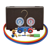
Ensure service ports are clean and free of metal shavings before connecting.
Confirm that both valves on the manifold gauge set are shut completely prior to hook-up.
Connect the blue adapter to the low side service port and the red adapter to the high side service port.
Start the engine and set the A/C mode selector to HIGH and fan to HIGH for diagnosis.
Verify that both manifold valves are shut completely before charging.
Connect the yellow hose to the refrigerant gas supply, following manufacturer instructions.
Slowly open the low side valve until pressure reaches 40 psi, do not exceed this limit.
Close the low side (blue) valve when charging is finished.
Ensure there is no refrigerant remaining in the A/C system before evacuation.
Attach adapters to the system, connect the yellow hose to the vacuum pump, and turn it on.
Open both low and high side manifold valves to evacuate the system.
After reaching 29" Hg vacuum, run the pump for an additional 20 minutes.
Close both manifold valves and check gauges to ensure the vacuum remains.
Identified as component 1 in the system schematic.
Identified as component 2 in the system schematic.
Identified as component 3 (yellow) in the system schematic.
Identified as component 4 (16mm diameter) in the system schematic.
Identified as component 5 (13mm diameter) in the system schematic.
| Model | 89660 |
|---|---|
| Category | Measuring Instruments |
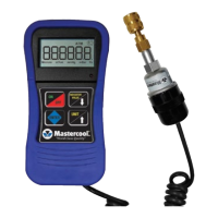
| Display | LCD |
| Battery | 9V |
| Type | Digital Manifold |
| Refrigerant Type | R-22, R-134a, R-404A |