Fig. 9
Fig. 10
1
4
1
3
5
2
2
4
3
CAUTION!
Make sure the tool rest is adjusted to be as close to the workpiece as possible. Rotate
the workpiece by hand to check clearance before starting the lathe.
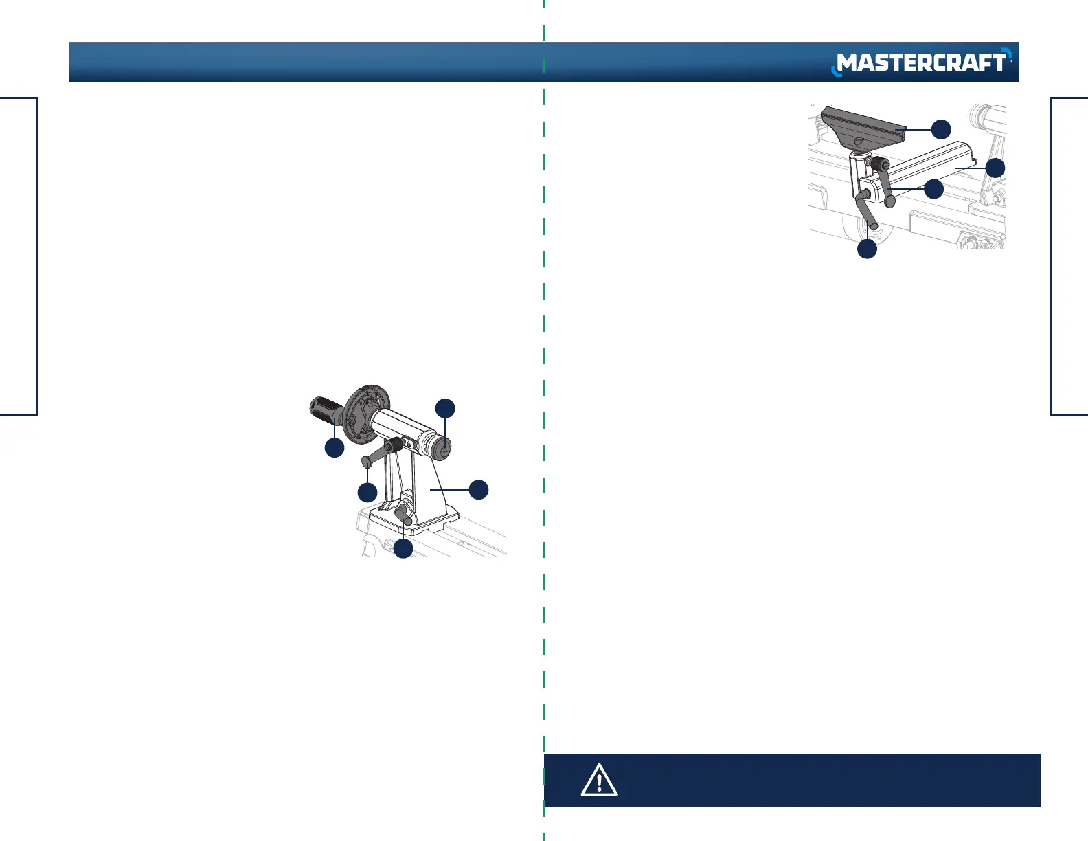
TAILSTOCK (Fig. 9)
• Move the tailstock (1) by loosening the
lock lever (2) and pushing the tailstock to
the desired position on the bed. Lock by
tightening the lock lever (2).
• The spindle can extend up to 2" (5 cm)
from the tailstock housing. Move the
tailstock spindle (3) by loosening the
spindle lock lever (4) and then turning
the hand wheel (5). Turning the hand
wheel clockwise extends the spindle;
turning it counter-clockwise retracts the
spindle. Lock levers (2, 4) before
operating the lathe.
• The tailstock spindle is hollow and can
be accessed from the handwheel end.
Use the push-out rod to remove the
centre cup or to drill holes through the
centre of a workpiece on a faceplate.
USING TOOL REST (Fig. 10)
• To move the tool rest base (1), loosen the
lock lever (2), and move the base to the
right or left and back or front.
Tighten the lever (2) when the tool rest
base is in the desired position.
• To adjust the angle of the tool rest (3),
loosen the lock lever (4), move the tool
rest to the desired position, and tighten
the lock lever.
• To change to the other tool rest, loosen
the lock lever (4) and pull the tool rest (3)
out of the tool rest base, insert the other
tool rest, adjust to desired position, and
tighten the lock lever (4).
• Move the switch to the On position to start the motor. Electric current is immediately
applied to the motor. Wait for the one-to-three-second second delay in activation
before the motor begins to drive the headstock spindle. The time it takes for the
motor to reach the speed set by the speed control knob depends on the size and
weight of the workpiece.
• Move the switch to the Off position to stop the motor. Electric current is immediately
disconnected, but the spindle and workpiece will continue to spin for a few
seconds.
RESET BUTTON (Fig. 8)
The reset button (4) will restart the motor after the motor shuts off due to overloading
or low voltage. If the motor stops during operation:
• Turn the On/Off switch (1) to the Off position and wait about five minutes for the
motor to cool.
• Press the reset button (4). Turn the switch (1) to the On position.
OPERATING INSTRUCTIONS
23
22
OPERATING INSTRUCTIONS
headline bars
continuation tabs
notes
warnings
headline bars
continuation tabs
notes
warnings
model no. 055-6793-6 | contact us 1-800-689-9928
 Loading...