Fig. 8
3
2
2
1
Fig. 8
1
4
CAUTION!
Never leave the lathe unattended until it has come to a complete stop.
WARNING!
If the motor shuts off unexpectedly, unplug the lathe from the power source, make
sure the On/Off switch is in the Off position, and allow the motor to cool down before
attempting to restart the lathe. Overheating may be caused by misaligned parts or a
dull chisel. Inspect the lathe for proper set-up before using it again.
NOTE:
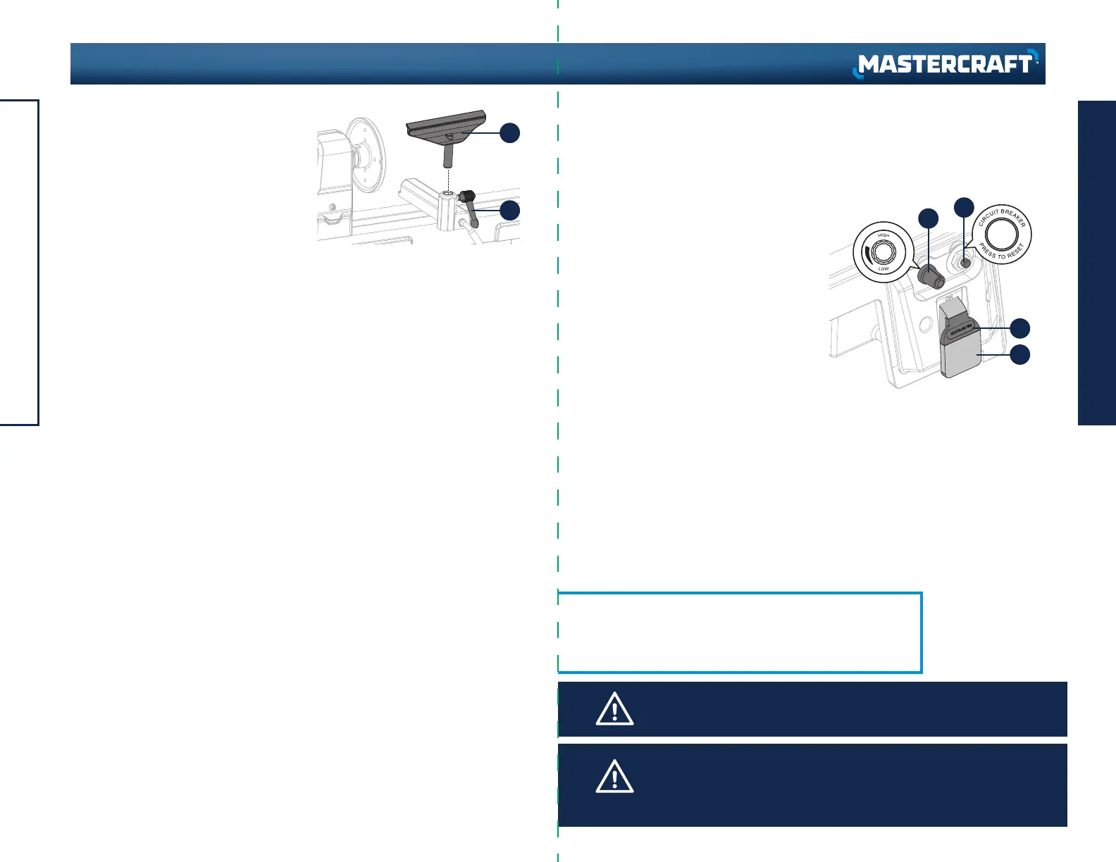
The safety key (3) can be removed from the switch when it is in
the Off position. With the key removed, the switch is locked in
that position and the lathe cannot be started. Store the key in a
safe place when the lathe is left idle (Fig. 8).
SPEED CONTROL KNOB (Fig. 8)
The speed control knob (1) is used to set
the speed of the lathe to suit the weight of
the workpiece or the type of tool being
used.
• After the lathe is started, turning the knob
clockwise will increase spindle speed (to
the maximum RPM).
Turning the knob counter-clockwise will
decrease spindle speed (to the minimum
RPM).
• Adjust the knob until the desired workpiece
rotation speed is reached.
INSTALLING TOOL REST (Fig. 8)
A 7” and a 4 1/2” tool rest are included.
• Loosen the lock lever (1).
• Insert the tool rest (2) into the tool rest
base.
• Tighten the lock lever (1).
VARIABLE SPEED CONTROL BOX
The variable speed control box contains the electrical connections to the motor, and
has three external controls—speed control knob, On/Off switch, and the
circuit-breaker reset button.
ON/OFF SWITCH (Fig. 8)
The On/Off switch (2) controls application of electrical power to the lathe’s motor.
The safety key (3) must be placed in the switch before the switch will operate.
OPERATING INSTRUCTIONS
21
20
ASSEMBLY INSTRUCTIONS
headline bars
continuation tabs
notes
warnings
headline bars
continuation tabs
notes
warnings
model no. 055-6793-6 | contact us 1-800-689-9928
 Loading...