3
2
1
1
3
2 1
Fig. 3
Fig. 4
Fig. 5 Fig. 6
Fig. 7
1
2
3
WARNING!
Do not operate the lathe until it is completely assembled and adjusted according to the
instructions.
NOTE:
The spring-loaded handles on the lathe are designed to minimize
interference with other lathe parts or the workpiece. To operate,
push the handle lever in and turn clockwise to tighten. Pulling
the handle lever outward will disengage the threaded shaft,
allowing you to reposition the lever handle so it is out of the way.
NOTE:
The faceplate has an open centre, so that when drilling through
a workpiece from the tailstock the drill bit can go completely
through the workpiece.
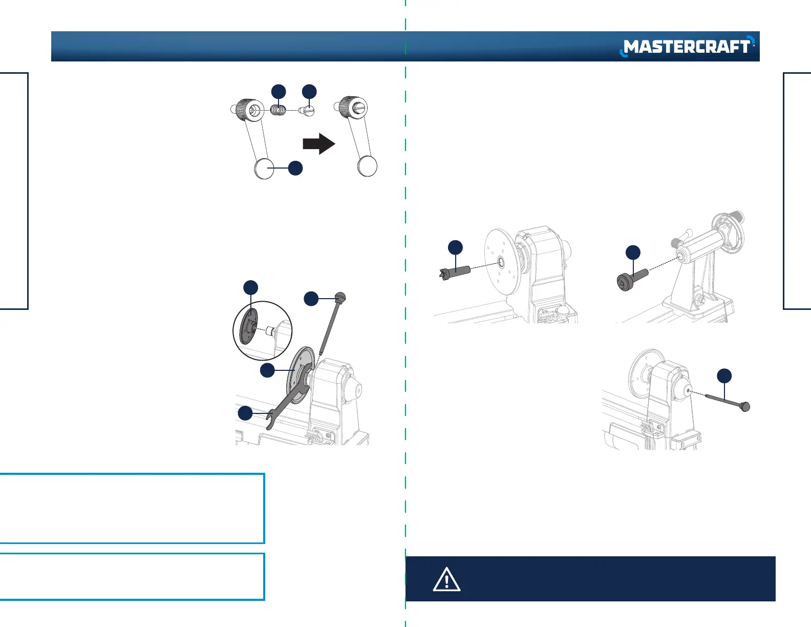
SPRING-LOADED LOCK LEVERS
(Fig. 3)
The spring-loaded lock levers for the
tailstock spindle and the tool rest are of
four-piece construction.
The shoulder screw (1) passes through the
spring (2) and the handle lever (3). If either
lock lever has come loose from the lathe or
has come apart in shipping, reassemble it
and thread into place.
INSTALLING OR REMOVING A
FACEPLATE (Fig. 4)
• When installing the faceplate (1), thread
faceplate onto the end of the headstock
spindle and hand tighten.
• Place the wrench (2) over the flats on the
faceplate.
• Insert the tip of the push-out rod (3) into
one of the slots in the side of the
headstock spindle.
REMOVING SPUR OR CENTRE
(Fig. 7)
• Insert the push-out rod (3) into the far
end of the headstock spindle or the
tailstock spindle until it comes into
contact with the shaft of the spur or
centre.
• Tap the end of the push-out rod (3) until
the spur or centre comes loose.
• Insert the shaft of the headstock spur
centre (1) into the hollow centre of the
headstock spindle (Fig. 5).
• Insert the shaft of the tailstock cup
centre (2) into the hollow centre of the
tailstock spindle (Fig. 6).
• While gripping the push-out rod firmly, turn the wrench to either tighten or loosen
the faceplate.
• Remove the push-out rod and wrench.
• If the faceplate is being removed, continue turning it until it comes off the spindle
threads.
INSTALLING SPUR AND CENTRE (Fig. 5-6)
• Insert the shaft of the headstock spur centre (1) into the hollow centre of the
headstock spindle (Fig. 5).
• Insert the shaft of the tailstock cup centre (2) into the hollow centre of the tailstock
spindle (Fig. 6).
USING A FACEPLATE
Mount the workpiece onto the faceplate with brass wood screws. Make sure the
screws are not so long that they will enter the area of the workpiece where material
is to be removed.
ASSEMBLY INSTRUCTIONS
19
18
ASSEMBLY INSTRUCTIONS
headline bars
continuation tabs
notes
warnings
headline bars
continuation tabs
notes
warnings
model no. 055-6793-6 | contact us 1-800-689-9928
 Loading...