9
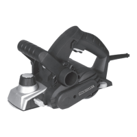
4. Slide the sharp blade face-up into
the blade-support block of the blade
barrel (10).
NOTE. The ridge along the blade
should be face away from the
clamping screws (11).
5. Evenly tighten the clamping screws
(11).
6. Repeat with the other blade.
NOTE: Always change the two blades at the same time, otherwise an
imbalance may occur and cause vibration and shorten the life of both the
blade and the tool.
NOTE: The blade position has been aligned at the manufactory, so do not
adjust the three inner hex screws on the blade supporter.
CAUTION: When installing blades, first clean out all chips and/or foreign
matter adhering to the blade barrel (10) and the blades themselves. Use
blades of the same dimensions and weight, or else the barrel will oscillate
and vibrate, causing poor planing action and tool breakdown. Tighten the
clamping screws (11) carefully when attaching the blades to the planer. A
loose clamping screw could be extremely dangerous. Regularly check to
ensure that the clamping screws are securely tightened.
NOTE: Your planing surface will end up rough and uneven unless the blades
are set properly and securely. The blades must be mounted so that the
cutting edge is absolutely level: parallel to the surface of the rear base (13).
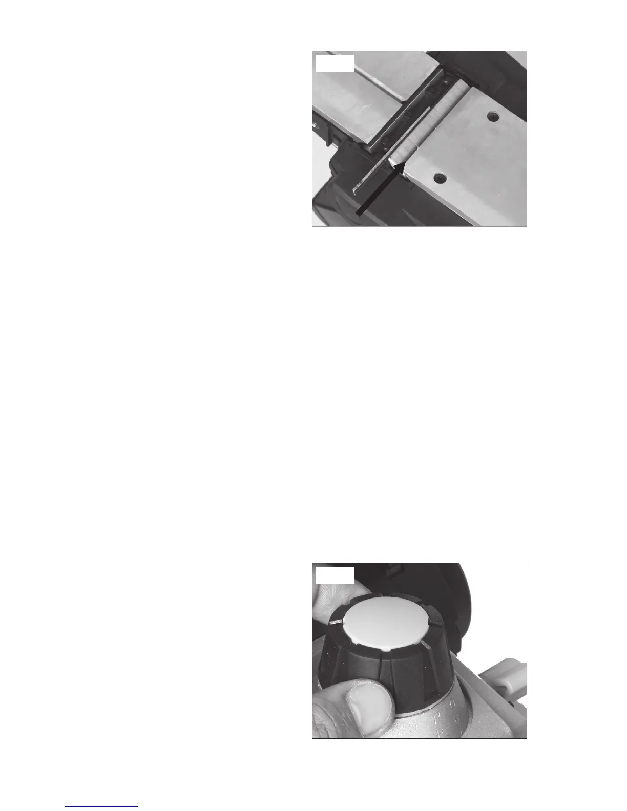
ADJUSTING THE DEPTH OF CUT (See Fig. 5)
CAUTION: Always ensure that the
tool is switched OFF and unplugged
from the power supply before making
adjustments or installing or removing
blades.
1. Rotate the depth-adjustment knob
(3) clockwise for a deeper cut
and counter-clockwise for a more
shallow cut.
2. The numbers on the ring under
the depth-adjustment knob indicate the depth of cut. For example, when
Fig. 4
Fig. 5