Page 6
OPERATION
CHARGE PROCEDURE
WARNING
Before use charge
the battery pack fully to make sure that
the battery pack can get the maximum run time.
This battery pack does not have a memory.
You can charge it all the time.
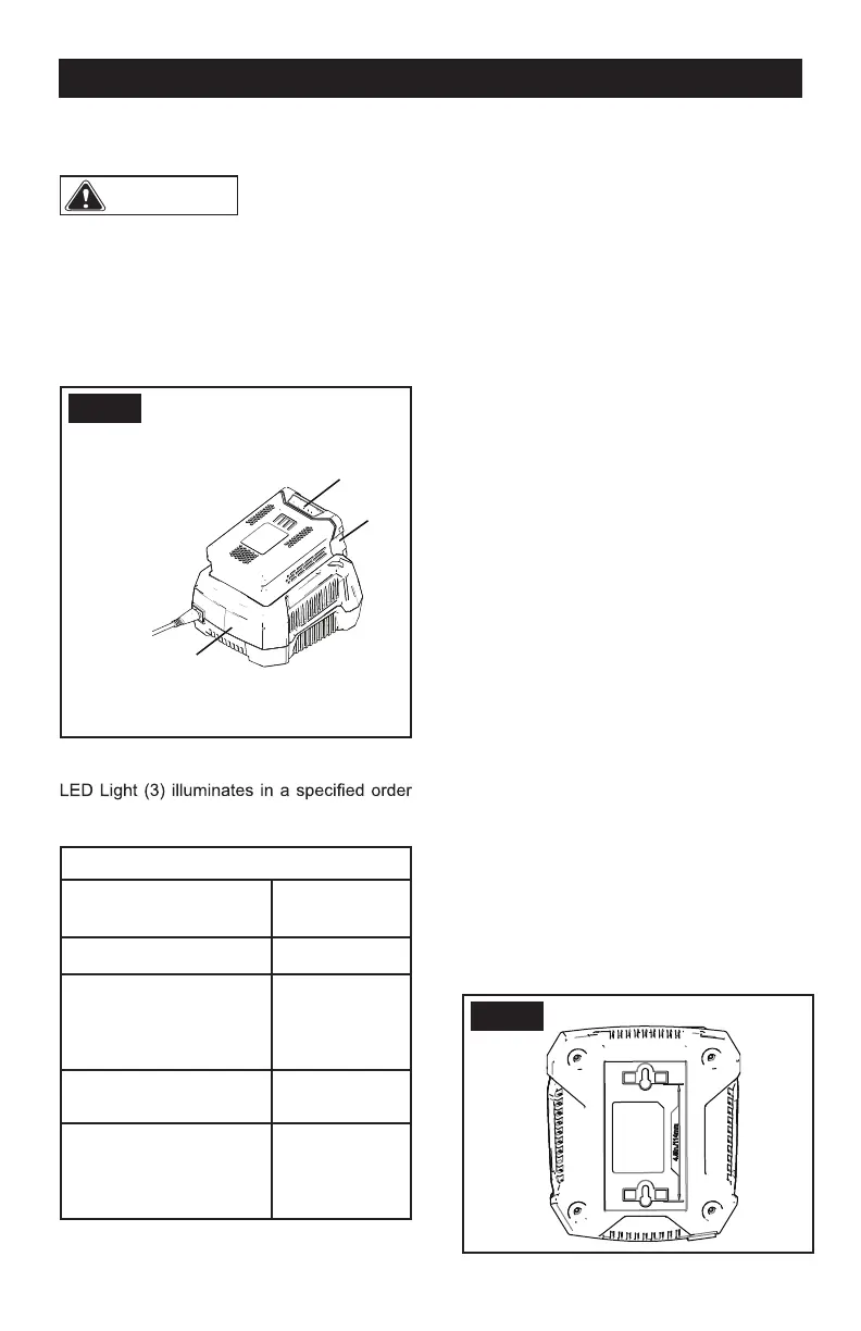
1. Connect the plug of charger (2) to an AC
power outlet.
2. Put the battery pack (1) into the charger (2).
FIG. 1
This is a diagnostic charger. The Charger
to show the current battery status. They are
as follows:
CHARGING PROCEDURE (LED INDICATOR)
BATTERY IS
CHARGING
GREEN
BLINKING
FULLY CHARGED GREEN
BATTERY IS TOO
WARM (REMOVE FOR
APPROX. 30 MINUTES
TO ALLOW TO COOL)
RED
NO BATTERY PRESENT RED
BLINKING
DEFECTIVE BATTERY
(REMOVE AND
REPLACE WITH A NEW
BATTERY)
RED
BLINKING
1. P
If the status LED RED flashes, remove the
battery pack from the charger for 1 minute.
ut the battery pack into the charger.
•
2. Put the battery pack into the charger again.
• If the status LED shows correct, the battery
pack is good.
• If the status LED RED stays blinking,
remove the battery pack and disconnect
the charger.
1
3
2
3. Wait for 1 minute and put the battery pack
into the charger again.
• If the status LED shows correct, the battery
pack is good.
• If the status LED RED stays blinking, the
battery pack is defective and it is necessary to
replace the battery pack.
EXAMINE THE CHARGER
If the battery pack does not charge correctly:
1. Examine the current of the power outlet
with different machines. Make sure that the
outlet works.
2. Examine that the charger contacts are not
short-circuited.
3. If the charger is not under usual room
temperature, move the charger and battery
pack to a locat
ion where the temperature is
between 6 ˚C and 40˚C.
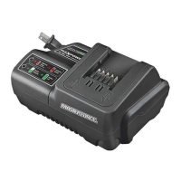
MOUNT THE CHARGER
1. This charger can be mounted on the wall
vertically using the holes on the bottom of
the charger. The holes are 4 1/2” (114mm)
apart.
2. If mounting on a exposed wood stud, use 2
wood screws placed 4 1/2” (114mm) apart to
mount the charger on the wood studs.
3. If mounting on drywall, drill two holes on a
vertical line 4 1/2” (114mm) apart and use wall
anchors and screws to mount the charger.
FIG. 2