INSTALLATION
EN / DC Master 24/12 50A / February 2015 5
3 INSTALLATION
3.1 BEFORE YOU START
WARNING
During installation and commissioning of the
DC Master, the Important Safety Instructions
are applicable at all times. See chapter 2 of
this manual.
Make sure that the battery voltage is the same as the
input voltage of the DC Master (24V battery for a 24V
input voltage).
Fuses must be integrated in the positive wires. These
fuse(s) shall be placed last of all. Recommended
fuses:
Recommended Fuse
Input fuse 50A
Output fuse 60A
Remote switch fuse 2A - T
Keep the cable connections as short as possible,
Recommended maximum length of the DC cables: 3 m
/ 10ft. If available, use coloured battery cables: Red for
positive, black for negative. Recommended wire
gauges:
AWG Metric
Input wires (24V) 8 AWG 10 mm²
Output wires (12V) 6 AWG 16 mm²
Remote switch (24V) 16 AWG 1.5 mm²
3.2
CHOOSING A LOCATION TO INSTALL
For an optimal optimum heat discharge, the DC Master
must be installed in a well-ventilated room protected
against rain, vapour, moisture and dust. We advise to
mount the unit in a vertical position with the connecting
cables downward.
Never use the DC Master at a location where there is
danger of gas or dust explosions.
Allow at least 10 cm / 4 inch space around the
apparatus.
Do not mount the DC Master straight above the
batteries because of possible corrosive fumes.
3.3 CONTENTS OF THE DELIVERY:
DC Master 24/12 50-60A
Mounting bracket
4x screws, 4x screw covers, 4x mounting spacers
A 5-way terminal block + wire bridge
This user’s manual;
If one of these items is missing, please contact your
supplier.
3.4 INSTALLATION STEP-BY-STEP
1 Carefully remove the mounting bracket from the DC
Master using a flat-blade screwdriver. Use the
provided screws and dowels to mount the bracket to a
solid and flat surface. Insert the DC Master in the
mounting bracket and press it down until it clicks into
place.
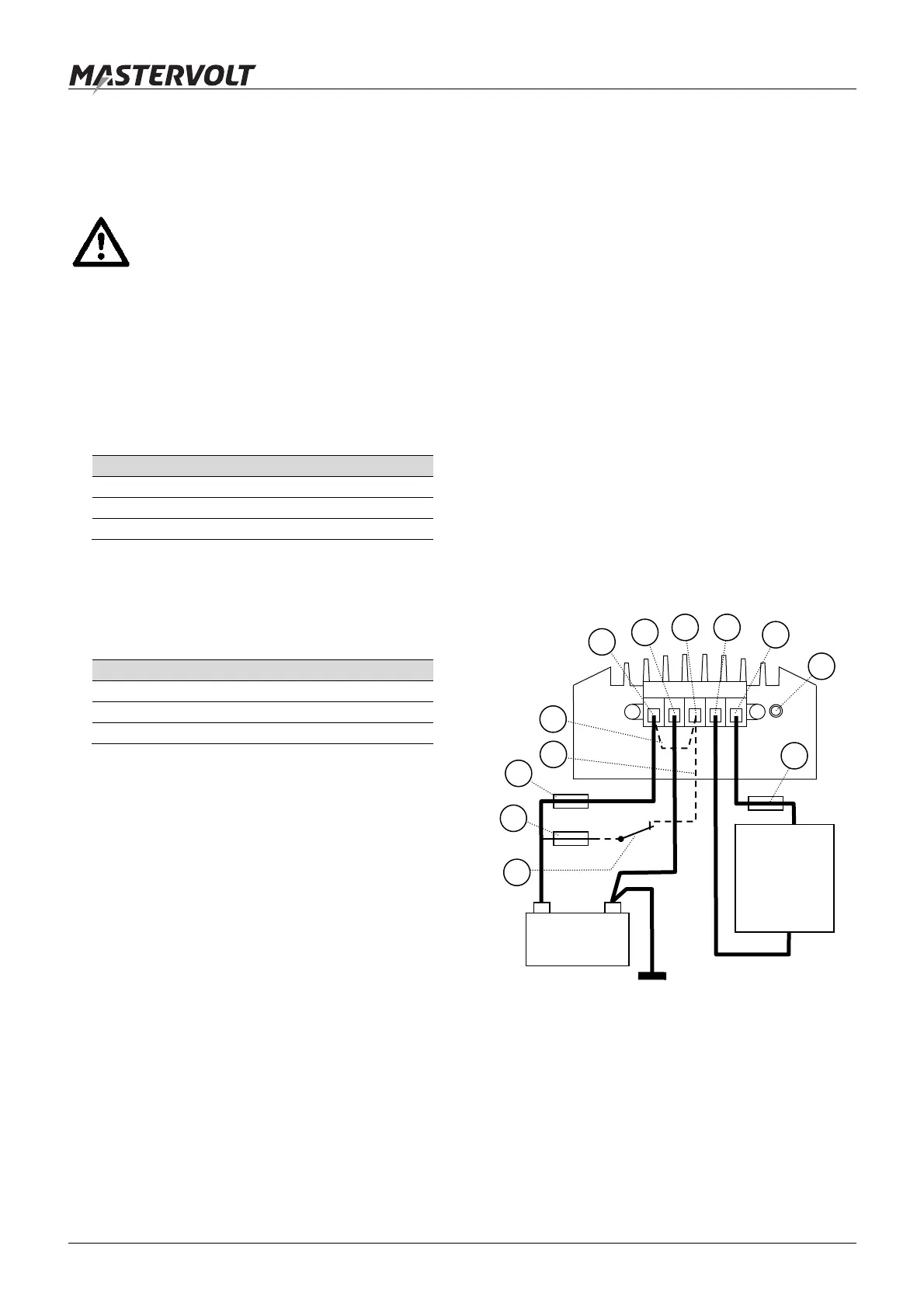
2 See figure 2. Connect the wires as indicated, but do
not place the DC fuse(s) yet. Connect the input wires
first, and then connect the output wires.
a. Without remote switch function: place the
supplied wire bridge between Enable contact (3)
and Positive input (1);
b. With remote switch function: remove the supplied
wire bridge and install Remote switch fuse (8)
and Remote switch (9) as indicated.
3 Check all wiring. If OK, place the DC fuse(s). When
the fuse is placed, internal capacitors may cause a
spark. This is normal.
1 = Positive input (27.2V) 6 = Status LED
2 = Negative input (0V) 7 = Input fuse
3 = Enable (Active high) 8 = Remote switch fuse
4 = Negative output (0V) 9 = Remote switch
5 = Positive output (13.6V) 10 = Output fuse
Figure 2: Wiring diagram
+ –
24V
Load
Belasting
Last
Charge
Carico
Car
a
+ 13.6V
–
1
2
3 4
5
6
7
8
9
10
a
b
 Loading...