EasyManuals Logo

Mastervolt Multipurpose Contact Output User Manual

Mastervolt Multipurpose Contact Output
4 pages
To Next Page IconTo Next Page
To Previous Page IconTo Previous Page
Page #3 background imageLoading...
Page #3 background image
Multipurpose Contact Output User and installation manual
3
Likewise, the Multipurpose Contact Output can control other devices. The following example shows how event
source "State" of the Multipurpose Contact Output, is used to control the feedback LED of a Digital Switch Input.
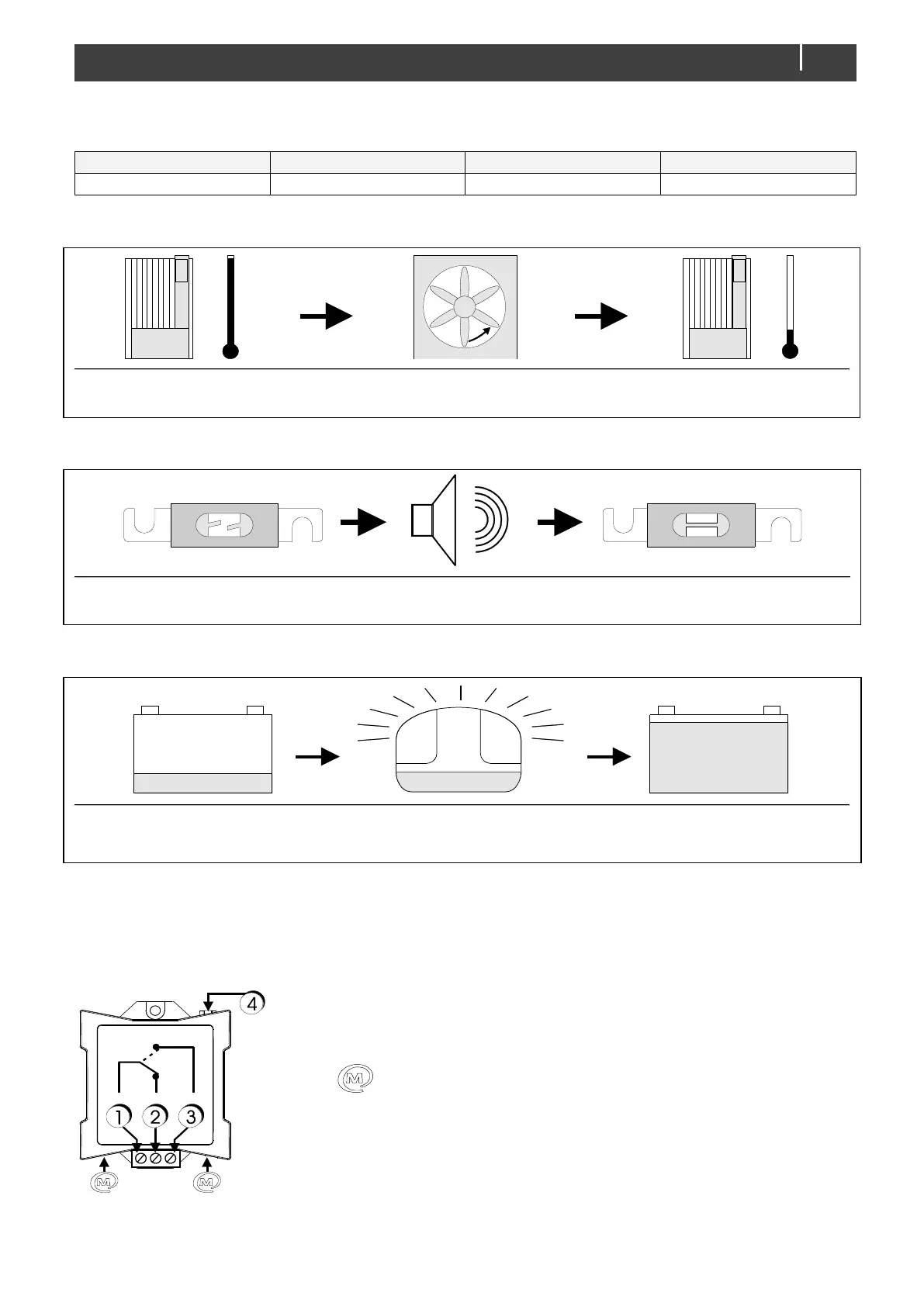
Event source
Event target
Event command
Event action
State
Switch input
Feed back 1
Copy
3. EXAMPLES
Where to configure: Mass Charger, Multipurpose contact controls: Fan
Where to configure: DC Distribution, Multipurpose contact controls: Buzzer
Where to configure: MasterShunt, Multipurpose contact controls: Generator
4. INSTALLATION
Insert the MasterBus cables, then connect the relay cables to the screw terminal input and outputs as
shown below.
Overview and functional scheme of the Multipurpose Contact Output
Source
Target
Command
Command Data
Temperature High
Multipurpose Contact
Activate
Copy
Source
Target
Command
Command Data
Fuse blown
Multipurpose Contact
Activate
Copy
Source
Target
Command
Command Data
Battery Low
Multipurpose Contact
Activate
Copy
1. Input
2. Output normally closed
3. Output normally open
4. Communication LED, illuminating when the state is “activate”
MasterBus connector
Function:
Stand by: 1 is connected to 2,
Activate: 1 is connected to 3,
Maximum relay current: 1A.

Questions and Answers:

Question and Answer IconNeed help?

Do you have a question about the Mastervolt Multipurpose Contact Output and is the answer not in the manual?

Mastervolt Multipurpose Contact Output Specifications

General IconGeneral
BrandMastervolt
ModelMultipurpose Contact Output
CategoryRelays
LanguageEnglish

Related product manuals