Dimensions in Inches(millimeters) mate.com
Mate Precision Technologies • 1295 Lund Boulevard • Anoka, Minnesota 55303 USA • Phone +1.763.421.0230 • 800.328.4492 • Fax +1.763.421.0285 • 800.541.0285
The Mate Logo is a registered trademark of Mate Precision Technologies Inc.
© Mate Precison Technologies Inc.
LIT01233 Rev B
MATE 2-PIN LINE UP TOOL
USAGE INSTRUCTIONS
ALIGNMENT PROCEDURE
This procedure is a continuation from step #6 of “Check Multi Tool Alignment” section
above for if alignment is needed.
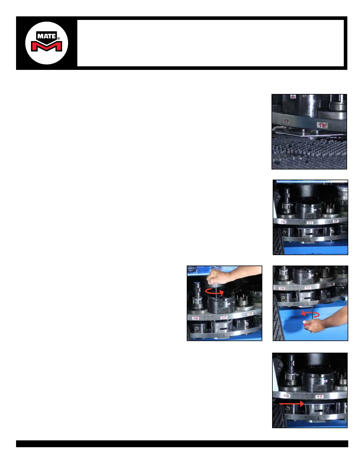
Step 1
Step 2
Step 3bStep 3a
1. Before rotating the turret to the tool change position, lift the Alignment Punch while
placing a piece of metal between the Alignment Punches and the Die or Die Carrier.
CAUTION: It is very important that the Alignment Punch Pins are NOT engaged with
the Die or Die Carrier when rotating the turret. Damage to the Alignment Tool and/or
turret is possible.
2. Once the piece of metal is in place, dis-engage the machine turret alignment pins and
rotate the station back to the tool change position.
3a. Flange Bolts: Loosen all bolts to be
slightly engaged on the Upper Assembly.
3a. Flange Bolts: Loosen all bolts to be
slightly engaged on the Lower Subplate.
4. With the station still rotated to the tool change position, place a piece of metal on top
of the alignment Die or Die Carrier to prevent any upper tools from engaging into the
Die or Die Carrier.
WARNING: It is very important that the Alignment Pins are NOT engaged with the Die
or Die Carrier holes when rotating the turret. Damage to the Alignment Tool and/or
turret is possible.
Step 4
 Loading...