Do you have a question about the Matek Systems F722-WING and is the answer not in the manual?
Lists key components like MCU, IMU, Baro, OSD, Blackbox, and connectivity features such as Uarts, Motors, Servos, I2C, and ADC inputs.
Details power input range, current sensing, and various BEC outputs for FC, camera/VTX, and servos, including voltage options.
Identifies battery and ESC power pads, ESC signal, and ground connections for motor control.
Details connections for Analog Airspeed, Buzzer, LED, RSSI, and I2C for compass/digital airspeed sensors.
Maps UART ports (1-6) and Softserial TX to specific pinouts for receiver, GPS, and VTX control.
Explains dual camera input switching and voltage selection (5V/9V) for cameras and VTX.
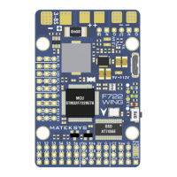
Describes the function of onboard LEDs for FC status and the Boot button for DFU mode.
Provides the physical size, weight, and mounting hole specifications of the flight controller.
Illustrates the connection of motors, servos, receiver, GPS, VTX, and other peripherals to the flight controller.
Details the default and configurable settings for UARTs, Softserial, and peripherals like GPS and Receiver.
Explains how to configure the Vsw power output for cameras or other accessories via RC channels.
| Brand | Matek Systems |
|---|---|
| Model | F722-WING |
| Category | Controller |
| Language | English |