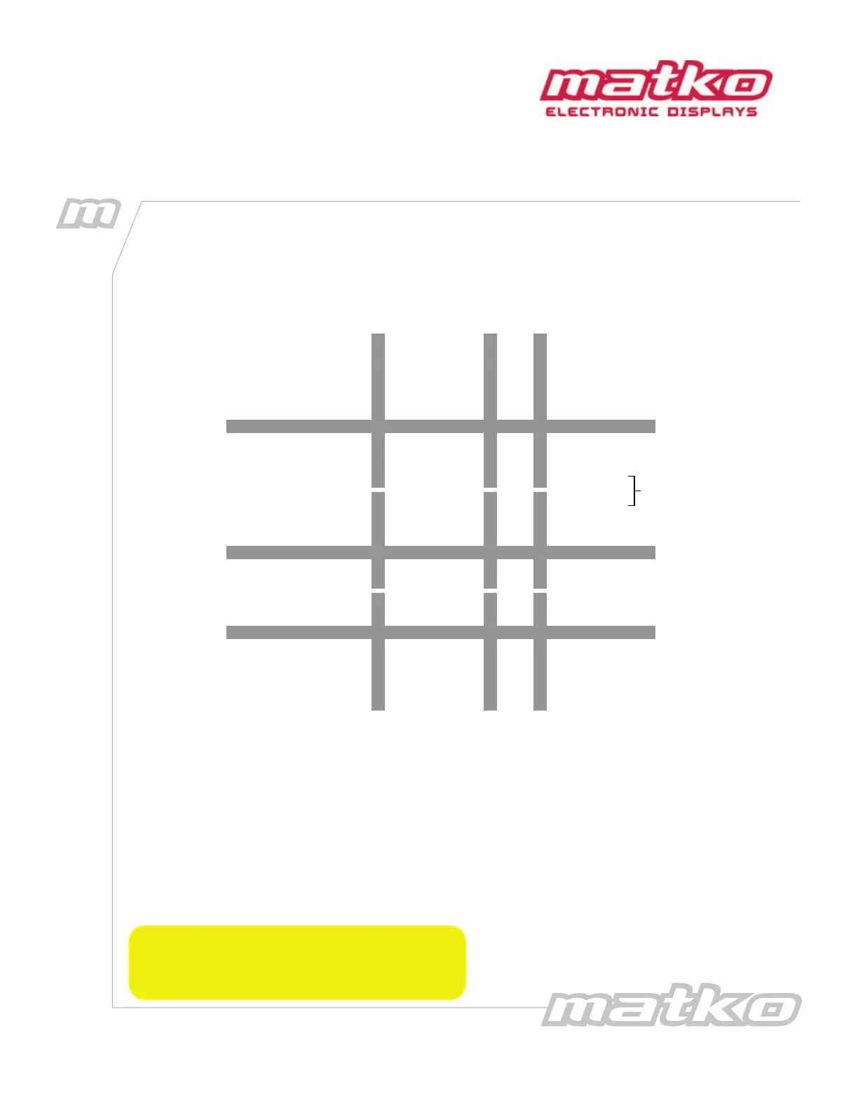
Section 2: Wiring Conguration
Connect the Scale indicator using the appropriate diagram to the BLACK
terminal block on the Input Card (See Figure 2.2).
6
7
+20mA
–20mA
Indicators with
Active 20 mA
Output
5
4
RX CL (+)
RX CL (–)
TX 422A (+)
TX 422B (–)
RX 422A
RX 422B
Indicators with
RS422 Output
3
2
TXD
GND
Indicators with
RS232 Output
232 RXD
GROUND
Indicator DisplayPin
1
2
4
5
+20mA
–20mA
VCC
GROUND
RC CL(–)
RX CL(+)
Indicators with
Passive 20 mA
Output
JUMP
Figure 2.1: Wiring Diagram
The corresponding green LED will blink with every data transmission.
Data Transmission (GREEN Terminal Block)
There is a hardware echo for Current Loop on GREEN Terminal Block pins 1 and 2
as well as a hardware RS 232 echo on pins 3 and 4. Any character received through the BLACK terminal block
automatically is sent out these 2 ports, allowing for a boosted signal. There are also two software ports for
data transmission. RS232 on Pins 4 and 5 and RS422 on pins 6 and 7 of the GREEN terminal block. See Option
18 for details
*DATA RELIABILITY in the following order:
RS422/485 (Up to 4000 feet)
Current Loop (Up to 2000 feet)
RS232 (Up to 50 feet)
5
Section 2:
Wiring Conguration
 Loading...